TPower I45 Setup Ma nua l FCC Information and Copyright This equipment has been tested and found to comply with the limits of a Class B digital device, pursuant to Part 15 of the FCC Rules. These limits are designed to provide reasonable protection against harmful interference in a residential installation. This equipment generates, uses, and can radiate radio frequency energy and, if not installed and used in accordance with the instructions, may cause harmful interference to radio communications.
Table of Contents Chapter 1: Introduction ............................................................ 1 1.1 Before You Start......................................................................................... 1 1.2 Package Checklist ..................................................................................... 1 1.3 Motherboard Features.............................................................................. 2 1.4 Rear Panel Connectors.......................................................
TPower I45 CHAPTER 1: INTRODUCTION 1.1 BEFORE YOU START Thank you for choosing our product. Before you start installing the motherboard, please make sure you follow the instructions below: 1.2 Prepare a dry and stable working environment with sufficient lighting. Always disconnect the computer from power outlet before operation.
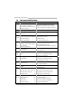
Motherboard Manual 1.3 MOTHERBOARD FEATURES SPEC LGA 775 CPU Supports Execute Disable Bit / Enhanced Intel Intel Core2Duo / Core2Quad / Pentium Dual-Core / Celeron Dual-Core / Celeron 4xx processor FSB Chipset Support 800 / 1066 / 1333 / 1600 MHz Intel ICH10R Environment Control initiatives, Provides the most commonly used legacy Hardware Monitor Controller Super I/O functionality.
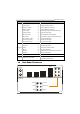
TPower I45 SPEC Front Audio Connector x1 CD-in Connector x1 Supports CD audio-in function S/PDIF out connector x2 Supports digital audio out function S/PDIF in connector x1 Supports digital audio-in function CPU Fan header x1 CPU Fan power supply (with Smart Fan function) System Fan header x2 System Fan Power supply Clear CMOS header x1 Restore CMOS data to factory default USB connector x3 Each connector supports 2 front panel USB ports Power Connector (24pin) x1 Connects to Power s
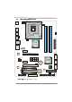
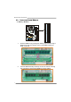
Motherboard Manual 1.5 MOTHERBOARD LAYOUT JKBMS1 JCFAN1 JATXPWR1 LGA775 CPU1 BIOS JUSB2 DDR2_B2 DDR2_B1 JUSBV1 DDR2_A2 ESATAX1 DDR2_A1 JUSB1 JATXPWR2 JNFAN1 JRJ45USB1 Intel P45 JAUDIO1 J1 PEX1_2 JCMOS1 PEX16_1 LAN JPE1 JPE3 JPE5 JPE7 SATA1 JSPDIF_OUT2 PEX1_1 JCDIN1 Intel ICH10R JPE2 JPE4 JPE6 JPE8 JPE9 BAT1 SATA2 PEX16_2 SATA3 CODEC PCI1 Super I/O JSPDIF_OUT1 PCI2 JAUDIOF1 JCOM1 IDE1 JUSBV2 JUSB5 JUSB4 JUSB3 FDD1 JSPDIF_IN1 Note: ■ represents the 1st pin.
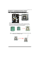
TPower I45 CHAPTER 2: HARDWARE INSTALLATION 2.1 INSTALLING CENTRAL PROCESSING UNIT (CPU) Special Notice: Remove Pin Cap before installation, and make good preservation for future use. When the CPU is removed, cover the Pin Cap on the empty socket to ensure pin legs won’t be damaged. Pin Cap Step 1: Pull the socket locking lever out from the socket and then raise the lever up to a 90-degree angle.
Motherboard Manual Step 2: Look for the triangular cut edge on socket, and the golden dot on CPU should point forwards this triangular cut edge. The CPU will fit only in the correct orientation. Step 2-1: Step 2-2: Step 3: Hold the CPU down firmly, and then lower the lever to locked position to complete the installation. Step 4: Put the CPU Fan and heatsink assembly on the CPU and buckle it on the retention frame. Connect the CPU FAN power cable into the JCFAN1. This completes the installation.
TPower I45 2.2 FAN HEADERS These fan headers support cooling-fans built in the computer. The fan cable and connector may be different according to the fan manufacturer. Connect the fan cable to the connector while matching the black wire to pin#1.
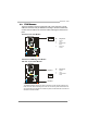
Motherboard Manual 2.3 INSTALLING SYSTEM MEMORY 8 DD R2_B1 DD R2_B2 DD R2_A1 DD R2_A2 A. Memory Modules 1. Unlock a DIMM slot by pressing the retaining clips outward. Align a DIMM on the slot such that the notch on the DIMM matches the break on the Slot. 2. Insert the DIMM vertically and firmly into the slot until the retaining chip snap back in place and the DIMM is properly seated.
TPower I45 B. Memory Capacity DIMM Socket Location DDR2 Module DDR2_A1 256MB/512MB/1GB/2GB DDR2_A2 256MB/512MB/1GB/2GB DDR2_B1 256MB/512MB/1GB/2GB DDR2_B2 256MB/512MB/1GB/2GB Total Memory Size Max is 8GB. C. Dual Channel Memory installation To trigger the Dual Channel function of the motherboard, the memory module must meet the following requirements: Install memory module of the same density in pairs, shown in the following table.
Motherboard Manual 2.4 CONNECTORS AND SLOTS FDD1: Floppy Disk Connector The motherboard provides a standard floppy disk connector that supports 360K, 720K, 1.2M, 1.44M and 2.88M floppy disk types. This connector supports the provided floppy drive ribbon cables. 33 1 34 2 IDE1: IDE/ATAPI Connector The motherboard has a 32-bit Enhanced PCI IDE Controller that provides PIO Mode 0~4, Bus Master, and Ultra DMA 33/66/100/133 functionality.
TPower I45 SATA1~SATA3: Serial ATA Connectors The motherboard has a PCI to SATA Controller with 6 channels SATA interface, it satisfies the SATA 2.0 spec and with transfer rate of 3.0Gb/s. SATA3 SATA2 SATA1 PCI1/PCI2: Peripheral Component Interconnect Slots This motherboard is equipped with 2 standard PCI slots. PCI stands for Peripheral Component Interconnect, and it is a bus standard for expansion cards. This PCI slot is designated as 32 bits.
Motherboard Manual PEX16_1: PCI-Express Gen2 x16(x16/CrossFire x8 Speed) Slot - - - PCI-Express 2.0 compliant. Maximum theoretical realized bandwidth of 8GB/s(4GB/s CrossFire) simultaneously per direction, for an aggregate of 16GB/s(8GB/s CrossFire) totally. PEX16_1 slot is reserved for graphics or video cards. The design of this motherboard supports dual PCI-Express graphics cards using CrossFire technology with multiple displays. When using CrossFire, this slot is master and runs with x8 speed.
TPower I45 CHAPTER 3: HEADERS & JUMPERS SETUP 3.1 HOW TO SETUP JUMPERS The illustration shows how to set up jumpers. When the jumper cap is placed on pins, the jumper is “close”, if not, that means the jumper is “open”. Pin opened 3.2 Pin closed Pin1-2 closed DETAIL SETTINGS JPANEL1: Front Panel Header This 16-pin connector includes Power-on, Reset, HDD LED, Power LED, and speaker connection. It allows user to connect the PC case’s front panel switch functions.
Motherboard Manual JATXPWR2: ATX Power Source Connector This connector allows user to connect 24-pin power connector on the ATX power supply. Pin 13 14 15 16 17 18 19 20 21 22 23 24 Assignment +3.3V -12V Ground PS_ON Ground Ground Ground NC +5V +5V +5V Ground 12 24 1 13 Pin 1 2 3 4 5 6 7 8 9 10 11 12 Assignment +3.3V +3.3V Ground +5V Ground +5V Ground PW_OK Standby Voltage+5V +12V +12V +3.
TPower I45 J1: Auxiliary Power for Graphics This connector is an auxiliary power connection for graphics cards. Exclusive power for the graphics card provides better graphics performance. Pin 1 4 1 2 3 4 Assignment +12V Ground Ground VCC JUSB3/JUSB4/JUSB5: Headers for USB 2.0 Ports at Front Panel This header allows user to connect additional USB cable on the PC front panel, and also can be connected with internal USB devices, like USB card reader.
Motherboard Manual JAUDIOF1: Front Panel Audio Header This header allows user to connect the front audio output cable with the PC front panel. This header allows only HD audio front panel connector; AC’97 connector is not acceptable.
TPower I45 JSPDIF_OUT1/JSPDIF_OUT2: Digital Audio-out Connectors JSPDIF_OUT1 is for connecting the PCI bracket SPDIF output, and JSPDIF_OUT2 is for connecting to the HDMI audio of VGA card. 1 Pin 1 2 3 Assignment +5V SPDIF_OUT Ground 3 JSPDIF_OUT2 JSPDIF_OUT1 3 1 JSPDIF_IN1: Digital Audio-in Connector This connector allows user to connect the PCI bracket SPDIF input header.
Motherboard Manual JCOM1: Serial port Connector The motherboard has a Serial Port Connector for connecting RS-232 Port.
TPower I45 JUSBV1/JUSBV2: Power Source Headers for USB Ports Pin 1-2 Close: JUSBV1: +5V for USB ports at JUSB1/JUSB2/JRJ45USB1. JUSBV2: +5V for USB ports at JUSB3/JUSB4/JUSB5. Pin 2-3 Close: JUSBV1: +5V STB for USB ports at JUSB1/JUSB2/ JRJ45USB1. JUSBV2: +5V STB for USB ports at JUSB3/JUSB4/JUSB5. 3 1 1 Pin 1-2 close 3 JUSBV1 JUSBV2 3 3 1 Pin 2-3 close 1 On-Board Buttons There are 2 on-board buttons. RSTSW2 PWRSW1 PWRSW1: This is an on-board Power Switch button.
Motherboard Manual BIOS POST Code/CPU Temperature Indicator This indicator will show POST code while booting; after the booting sequence, it will show current CPU temperature. Please refer to Chapter 7.4 for all the BIOS POST codes. JPE1~JPE9: CrossFire Switch Jumpers The setting of these jumpers determines the operation mode of PEX16_1 and PEX16_2. If you want to use the CrossFire function, these jumpers should be set to Pin 2-3 close; and PEX16_1 and PEX16_2 will both run with x8 speed.
TPower I45 CHAPTER 4: CROSSFIRE FUNCTION 4.1 REQUIREMENTS Only Windows XP/Vista supports CrossFire (Dual Video) function. Two identical CrossFire-ready graphics cards that are ATI certified. The graphics card driver should support CrossFire technology. The power supply unit must provide at least the minimum power required by the system, or the system will be unstable. A power supply above 500W is recommended under CrossFire mode. 4.
Motherboard Manual Step 2: Insert the two CrossFire-Ready graphics cards into PEX16_1 (Master) and PEX16_2 (Slave) PEX16_1(Mas ter ) PEX16_2(Slave) Notice: Make sure both the graphics cards are seated into slots completely. Step 3: Connect a 4-pin ATX power cable to Auxiliary Power Connector (J1), this will ensure the stabilization of your system. Step 4: Connect the CrossFire Bridge with two graphics cards. Installation completes.
TPower I45 CHAPTER 5: RAID FUNCTIONS 5.1 OPERATION SYSTEM Supports Windows 2000 Professional, Windows XP, and Windows VISTA. 5.2 RAID ARRAYS RAID supports the following types of RAID arrays: RAID 0: RAID 0 defines a disk striping scheme that improves disk read and write times for many applications. RAID 1: RAID 1 defines techniques for mirroring data. RAID 1+0 (Onboard): RAID 1+0 combines the techniques used in RAID 0 and RAID 1.
Motherboard Manual RAID 1: Every read and write is actually carried out in parallel across 2 disk drives in a RAID 1 array system. The mirrored (backup) copy of the data can reside on the same disk or on a second redundant drive in the array. RAID 1 provides a hot-standby copy of data if the active volume or drive is corrupted or becomes unavailable because of a hardware failure.
TPower I45 RAID 1+0 (For Onboard SATA Only): RAID 1 drives can be stripped using RAID 0 techniques. Resulting in a RAID 1+0 solution for improved resiliency, performance and rebuild performance. Features and Benefits Drives: Minimum 4, and maximum is 6 or 8, depending on the platform. Benefits: Optimizes for both fault tolerance and performance, allowing for automatic redundancy. May be simultaneously used with other RAID levels in an array, and allows for spare disks.
Motherboard Manual RAID 5 (For Onboard SATA Only): RAID 5 stripes both data and parity information across three or more drives. It writes data and parity blocks across all the drives in the array. Fault tolerance is maintained by ensuring that the parity information for any given block of data is placed on a different drive from those used to store the data itself. Features and Benefits Drives: Minimum 3. Uses: RAID 5 is recommended for transaction processing and general purpose service.
TPower I45 CHAPTER 6: T-POWER BIOS & SOFTWARE 6.1 T-POWER BIOS T-Power BIOS Features Overclocking Navigator Engine (O.N.E.) Memory Integration Test (M.I.T., under Overclock Navigator Engine) BIO-Flasher: Update BIOS file from USB Flash Drive or FDD Self Recovery System (S.R.S) Smart Fan Function CMOS Reloading Program !! WARNING !! For better system performance, the BIOS firmware is being continuously updated.
Motherboard Manual Manual Overclock System (M.O.S.) MOS is designed for experienced overclock users. It allows users to customize personal overclock settings. Main Advanced PCIPnP BIOS SETUP UTILITY Boot Chipset O.N.E Over-Clocking Navigator setting Exit Options WARNING: Setting wrong values in below sections may cause system to malfunction.
TPower I45 FSB(Bsel) To NorthBridge Latch This item allows you to select the FSB Frequency. DRAM Frequency To get better system performance, sometimes downgrading the memory frequency is necessary when CPU frequency is adjusted over the upper limit. DDR2 Enhanced Mode This item allows you to control the DDR2 ram enhanced mode. DRAM Timing Configuration Enter this item for more advanced DRAM timing settings. Clock Gen Configuration Enter this item for more advanced Clock Gen settings.
Motherboard Manual V6 Tech Engine This engine will make a good over-clock performance. Main Advanced PCIPnP BIOS SETUP UTILITY Boot Chipset Exit O.N.E Over-Clocking Navigator setting Options WARNING: Setting wrong values in below sections may cause system to malfunction.
TPower I45 Notices: Not all types of Intel CPU perform above overclock setting ideally; the difference will be based on the selected CPU model. B. Memory Integration Test (M.I.T.) This function is under “Overclocking Navigator Engine” item. MIT allows users to test memory compatibilities, and no extra devices or software are needed. Step 1 The default setting under this item is “Disabled”; the condition parameter should be changed to “Enable” to proceed this test.
Motherboard Manual C. BIO-Flasher BIO-Flasher is a BIOS flashing utility providing you an easy and simple way to update your BIOS via USB pen drive or floppy disk. The BIO-Flasher is built in the BIOS chip. To enter the utility, press during the Power-On Self Tests (POST) procedure while booting up. Updating BIOS with BIO-Flasher 1. Go to the website to download the latest BIOS file for the motherboard. 2. Then, save the BIOS file into a USB pen drive or a floppy disk. 3.
TPower I45 D. Self Recovery System (S.R.S.) This function can’t be seen under BIOS setup; and is always on whenever the system starts up. However, it can prevent system hang-up due to inappropriate overclock actions. When the system hangs up, S.R.S. will automatically log in the default BIOS setting, and all overclock settings will be re-configured. E. Smart Fan Function Smart Fan Function is under “Smart Fan Configuration” in “Advanced Menu”.
Motherboard Manual Smart Fan Calibration Choose this item and then the BIOS will automatically test and detect the CPU/System fan functions and show CPU/System fan speed. Fan Ctrl OFF(℃) If the CPU/System temperature is lower than the set value, the CPU/ System fan will turn off. The range is from 0~127, with an interval of 1. Fan Ctrl On(℃) The CPU/System fan starts to work when CPU/System temperature arrives to this set value. The range is from 0~127, with an interval of 1.
TPower I45 6.2 T-POWER SOFTWARE T-Power2 is an integration of four functions: OC Tweaker for over-clock, eHot-Line for technical support, BIOS-watch for system monitor, and Biostar Flash for BIOS update. Installing T-Power2 1. Insert the Setup CD to the optical drive. The drivers installation program would appear if the Autorun function has been enabled. 2. Select Software Installation, and then click on T-Power2. 3. Follow the on-screen instructions to complete the installation.
Motherboard Manual OC Tweaker On the main panel, you can click on the OC Tweaker button to launch this function. The OC Tweaker provides automatic/manual over-clock function for BIOSTAR motherboard, and even for some BIOSTAR VGA card (VR8xxx series only) which is powered by V-Ranger.
TPower I45 By this function, the utility will set the best and stable performance and frequency automatically. Click on then a Warning dialog will show. This dialog tells that all running applications should be closed before the auto over-clock procedure. The utility will do a series of test continually; do not do any operation during the test procedure. Click OK to proceed or Cancel to stop.
Motherboard Manual E X: This means V9 engine is acti vated. By clicking , the utility would over-clock the system with certain fixed percentage. When the V3/V6/V9/V12/V15 engine is activated, you will see the green light bar on the left rising to the top of the button. This function is recommended for any inexperienced users. You can save current setting to a file by clicking will show.
TPower I45 BIO-watch BIO-watch is a control and monitor utility that helps you to maintain the health of the PC. It provides real-time information of CPU/GPU/System temperature, fan speed, and voltage; and fan control function.
Motherboard Manual Increase Speed Auto-Control OFF Decrease Speed Click the auto-control off and then the adjust level will show; use the level to increase/decrease the fan speed. Be aware if the fan level been down to 0%, the fan will still not completely stop; this is for your system’s protection. Click to enter the fan control setting dialog.
TPower I45 eHot-Line eHot-Line is a convenient utility that helps you to contact with our Tech-Support system. This utility will collect the system information which is useful for analyzing the problem you may have encountered, and then send these information to our tech-support department to help you fix the problem. Before you use this utility, please set Outlook Express as your default e-mail client application program.
Motherboard Manual After filling up this information, click “Send” to send the mail out. A warning dialog would appear asking for your confirmation; click “Send” to confirm or “Do Not Send” to cancel. If you want to save this information to a .txt file, click “Save As…” and then you will see a saving dialog appears asking you to enter file name. Enter the file name and then click “Save”. Your system information will be saved to a .txt file. Open the saved .
TPower I45 Biostar Flash Biostar Flash is a convenient utility which allows you to update your motherboard BIOS under Windows system. Shows curr ent BIOS infor mati on Restart Your System (AMI BIOS) Clear CMOS function (Award BIOS) Update BIOS with a B IOS fil e or Save current BIOS to a .bi n file Once click on this button, the saving dialog will show. Choose the position to save file and enter file name.
Motherboard Manual Before doing this, please download the proper BIOS file from our website: www.biostar.com.tw Update BIOS procedure should be run with Clear CMOS (or Restart) function, so please check on Clear CMOS (or Restart) first. (Restart Your System) Then click Update BIOS button, a dialog will show for asking you backup current BIOS. Click Yes for BIOS backup and refer to the Backup BIOS procedure; or click No to skip this procedure.
TPower I45 CHAPTER 7: USEFUL HELP 7.1 DRIVER INSTALLATION NOTE After you installed your operating system, please insert the Fully Setup Driver CD into your optical drive and install the driver for better system performance. You will see the following window after you insert the CD The setup guide will auto detect your motherboard and operating system. Note: If this window didn’t show up after you insert the Driver CD, please use file browser to locate and execute the file SETUP.
Motherboard Manual 7.2 EXTRA INFORMATION CPU Overheated If the system shutdown automatically after power on system for seconds, that means the CPU protection function has been activated. When the CPU is over heated, the motherboard will shutdown automatically to avoid a damage of the CPU, and the system may not power on again. In this case, please double check: 1. The CPU cooler surface is placed evenly with the CPU surface. 2. CPU fan is rotated normally. 3.
TPower I45 7.3 AMI BIOS BEEP CODE Boot Block Beep Codes Number of Beeps 1 2 3 4 5 7 10 11 12 13 Description No media present. (Insert diskette in floppy drive A:) “AMIBOOT.ROM” file not found in root directory of diskette in A: Insert next diskette if multiple diskettes are used for recovery Flash Programming successful File read error No Flash EPROM detected Flash Erase error Flash Program error “AMIBOOT.
Motherboard Manual 7.4 AMI BIOS POST CODE Checkpoint 03 04 05 06 07 08 C0 C1 C2 C5 C6 C7 0A 0B 0C 0E 13 20 24 2A 2C 2E 31 33 48 Description Disable NMI, Parity, video for EGA, and DMA controllers. Initialize BIOS, POST, Runtime data area. Also initialize BIOS modules on POST entry and GPNV area. Initialized CMOS as mentioned in the Kernel Variable "wCMOSFlags." Check CMOS diagnostic byte to determine if battery power is OK and CMOS checksum is OK.
TPower I45 Checkpoint 37 38 39 3A 3B 3C 40 52 60 75 78 7C 84 85 87 8C 8D 8E 90 A1 A2 A4 A7 A9 AA AB AC B1 00 Description Displaying sign-on message, CPU information, setup key message, and any OEM specific information. Initializes different devices through DIM. See DIM Code Checkpoints section of document for more information. USB controllers are initialized at this point. Initializes DMAC-1 & DMAC-2. Initialize RTC date/time. Test for total memory installed in the system.
Motherboard Manual 7.5 TROUBLESHOOTING Probable Solution 1. No power to the system at all 1. Make sure power cable is Power light don’t illuminate, fan securely plugged in. inside power supply does not turn 2. Replace cable. on. 3. Contact technical support. 2. Indicator light on keyboard does not turn on. System inoperative. Keyboard lights Using even pressure on both ends of are on, power indicator lights are lit, the DIMM, press down firmly until the and hard drive is spinning.
TPower I45 This page is intentionally left blank.
Motherboard Manual APPENDENCIES: SPEC IN OTHER LANGUAGE GERMAN Spezifikationen LGA 775 CPU Unterstützt Execute Disable Bit / Enhanced Intel Intel Intel Core2Duo / Core2Quad / Pentium Dual-Core / Celeron Dual-Core / Celeron 4xx Prozessoren FSB Chipsatz Memory 64 Technology / Virtualization Technology 800 / 1066 / 1333 / 1600 MHz Intel P45 Intel ICH10R Fintek F71887F Super E/A SpeedStep® / Intel Architecture-64 / Extended Umgebungskontrolle, Bietet die häufig verwendeten alten Super Hardware-Überwac
TPower I45 Spezifikationen Diskettenlaufwerkanschluss x1 Serieller Anschluss x1 IDE-Anschluss x1 Jeder Anschluss unterstützt 2 IDE-Laufwerke SATA-Anschluss x6 Jeder Anschluss unterstützt 1 SATA-Laufwerk Fronttafelanschluss x1 Unterstützt die Fronttafelfunktionen Front-Audioanschluss x1 Unterstützt die Fronttafel-Audioanschlussfunktion CD-IN-Anschluss x1 Unterstützt die CD Audio-In-Funktion S/PDIF Ausgangsanschluss x2 Unterstützt die digitale Audioausgabefunktion x1 Unterstützt die dig
Motherboard Manual FRANCE SPEC LGA 775 UC Prend en charge les technologies d'exécution de bit de Processeurs Intel Core2Duo / Core2Quad désactivation / Intel SpeedStep® optimisée/ / Pentium Dual-Core / Celeron Dual-Core / d'architecture Intel 64 / de mémoire étendue 64 / de Celeron 4xx virtualisation Bus frontal 800 / 1066 / 1333 / 1600 MHz Chipset Super E/S Intel P45 Intel ICH10R Fintek F71887F Initiatives de contrôle environnementales, Fournit la fonctionnalité de Super E/S Moniteur de matériel
TPower I45 SPEC Connecteur de disquette x1 Port série x1 Connecteur IDE x1 Connecteur SATA x6 Connecteur du panneau avant Chaque connector prend en charge 2 lecteurs de disquettes Chaque connecteur prend en charge 2 périphériques IDE Chaque connecteur prend en charge 1 périphérique SATA x1 Prend en charge les équipements du panneau avant Connecteur Audio du panneau avant x1 Prend en charge la fonction audio du panneau avant Connecteur d'entrée CD x1 Prend en charge la fonction d'entrée audi
Motherboard Manual ITALIAN SPECIFICA LGA 775 CPU FSB Chipset Supporto di Execute Disable Bit / Enhanced Processore Intel Core2Duo / Core2Quad Intel SpeedStep® / Architettura Intel 64 / / Pentium Dual-Core / Tecnologia Extended Memory 64 / Tecnologia Celeron Dual-Core / Celeron 4xx Virtualization 800 / 1066 / 1333 / 1600 MHz Intel P45 Intel ICH10R Fintek F71887F Super I/O Funzioni di controllo dell’ambiente: Fornisce le funzionalità legacy Super I/O Monitoraggio hardware usate più comunemente.
TPower I45 SPECIFICA Connettore floppy x1 Ciascun connettore supporta 2 unità Floppy Porta seriale x1 Connettore IDE x1 Ciascun connettore supporta 2 unità IDE Connettore SATA x6 Ciascun connettore supporta 1 unità SATA Connettore pannello frontale x1 Supporta i servizi del pannello frontale Connettore audio frontale x1 Supporta la funzione audio pannello frontale Connettore CD-in x1 Supporta la funzione input audio CD Connettore output SPDIF x2 Supporta la funzione d’output audio digi
Motherboard Manual SPANISH Especificación Admite Bit de deshabilitación de ejecución / Intel LGA 775 CPU Procesador Intel Core2Duo / Core2Quad / SpeedStep® Mejorado / Intel Architecture-64 / Pentium Dual-Core / Celeron Dual-Core / Tecnología Extended Memory 64 / Tecnología de virtualización Celeron 4xx FSB 800 / 1066 / 1333 / 1600 MHz Conjunto de Intel P45 chips Intel ICH10R Iniciativas de control de entorno, Fintek F71887F Súper E/S Le ofrece las funcionalidades heredadas de Monitor hardware uso m
TPower I45 Especificación Conector disco flexible X1 Puerto serie X1 Conector IDE X1 Cada conector soporta 2 dispositivos IDE Conector SATA X6 Cada conector soporta 1 dispositivos SATA Conector de panel frontal X1 Soporta instalaciones en el panel frontal Conector de sonido frontal X1 Soporta funciones de sonido en el panel frontal Conector de entrada de CD X1 Soporta función de entrada de sonido de CD Conector de salida S/PDIF X2 Soporta función de salida de sonido digital X1 Soporta
Motherboard Manual PORTUGUESE ESPECIFICAÇÕES LGA 775 CPU Processador Intel Core2Duo / Core2Quad / Pentium Dual-Core / Celeron Dual-Core / Celeron 4xx FSB Chipset o Super I/O Intel ICH10R Iniciativas para controlo do ambiente Proporciona as funcionalidades mais utilizadas em termos da especificação Super I/O.
TPower I45 ESPECIFICAÇÕES Conectores na placa Conector da unidade de disquetes x1 Porta série x1 Cada conector suporta 2 unidades de disquetes Conector IDE x1 Cada conector suporta 2 dispositivos IDE Conector SATA x6 Cada conector suporta 1 dispositivo SATA Conector do painel frontal x1 Para suporte de várias funções no painel frontal Conector de áudio frontal x1 Suporta a função de áudio no painel frontal Conector para entrada de CDs x1 Suporta a entrada de áudio a partir de CDs Conec
Motherboard Manual POLISH SPEC LGA 775 Procesor Procesor Intel Core2Duo / Core2Quad / Pentium Dual-Core / Celeron Dual-Core / Celeron 4xx FSB Chipset SpeedStep® / Intel Architecture-64 / Extended Memory 64 Technology / Virtualization Technology 800 / 1066 / 1333 / 1600 MHz Intel P45 Intel ICH10R Gniazda DDR2 DIMM x 4 Pamięć Każde gniazdo DIMM obsługuje moduły główna 256MB / 512MB / 1GB / 2GB Moduł pamięci DDR2 z trybem podwójnego kanału Obsługa DDR2 1066 / 800 / 667 Brak obsługi Registered DIMM or
TPower I45 SPEC Złącze napędu dyskietek Złącza wbudowane x1 Każde złącze obsługuje 2 napędy dyskietek Port szeregowy x1 Złącze IDE x1 Każde złącze obsługuje 2 urządzenia IDE Złącze SATA x6 Każde złącze obsługuje 1 urządzenie SATA Złącze panela przedniego x1 Obsługa elementów panela przedniego Przednie złącze audio x1 Obsługa funkcji audio na panelu przednim Złącze wejścia CD x1 Obsługa funkcji wejścia audio CD Złącze wyjścia S/PDIF x2 Obsługa funkcji cyfrowego wyjścia audio Złącze we
Motherboard Manual RUSSIAN СПЕЦ CPU LGA 775 Поддержка технологий Execute Disable Bit / (центральн Процессор Intel Core2Duo / Core2Quad / Enhanced Intel SpeedStep® / Intel Architecture-64 ый / Extended Memory 64 Technology / технологии Pentium Dual-Core / Celeron Dual-Core / процессор) Celeron 4xx FSB 800 / 1066 / 1333 / 1600 МГц Набор Intel P45 виртуализация микросхем Intel ICH10R Основная память Super I/O Слоты DDR2 DIMM x 4 Модуль памяти с двухканальным режимом DDR2 Каждый модуль DIMM по
TPower I45 СПЕЦ Разъём НГМД x1 Последовательный порт x1 Разъём IDE x1 Каждый разъём поддерживает 2 встроенных интерфейса накопителей Разъём SATA x6 Каждый разъём поддерживает 1 устройство SATA Разъём на лицевой панели x1 Поддержка устройств на лицевой панели Входной звуковой разъём x1 Разъём ввода для CD x1 Поддержка функции ввода для CD Разъём вывода для S/PDIF x2 Поддержка вывода цифровой звуковой функции x1 Поддержка ввода цифровой звуковой функции Встроенны Разъём ввода для S/PDIF
Motherboard Manual ARABIC اﻟﻤﻮاﺻﻔﺎت LGA 775 Execute Disable Bit / Enhanced Intelﺗﺪﻋﻢ ﺗﻘﻨﻴﺎت وﺣﺪة اﻟﻤﻌﺎﻟﺠﺔ Intel Core2Duo / Core2Quad /ﻣﻌﺎﻟﺠﺎت SpeedStep® / Intel Architecture-64 / Extended اﻟﻤﺮآﺰیﺔ Pentium Dual-Core / Celeron Dual-Core / Memory 64 Technology / Virtualization ﺑﺘﺮدد یﺼﻞ إﻟﻰ Celeron 4xx Technology اﻟﻨﺎﻗﻞ اﻷﻣﺎﻣﻲ اﻟﺠﺎﻥﺒﻲ ﻣﻴﺠﺎ هﺮﺗﺰ 800 / 1066 / 1333 / 1600ﺗﺮدد ﻣﺠﻤﻮﻋﺔ اﻟﺸﺮاﺋﺢ Intel P45 Intel ICH10R ﻓﺘﺤﺔ DDR2 DIMM اﻟﺬاآﺮة
TPower I45 اﻟﻤﻮاﺻﻔﺎت ﻣﻨﻔﺬ ﻣﺤﺮك أﻗﺮاص ﻣﺮﻥﺔ ﻋﺪد 1 ﻣﻨﻔﺬ ﺗﺴﻠﺴﻠﻲ ﻋﺪد1 ﻣﻨﻔﺬ IDE ﻋﺪد 1 IDEیﺪﻋﻢ آﻞ ﻣﻨﻔﺬ اﺙﻨﻴﻦ ﻣﻦ أﺝﻬﺰة ﻣﻨﻔﺬ SATA ﻋﺪد 6 SATAیﺪﻋﻢ آﻞ ﻣﻨﻔﺬ واﺣﺪ ﻣﻦ أﺝﻬﺰة ﻣﻨﻔﺬ اﻟﻠﻮﺣﺔ اﻷﻣﺎﻣﻴﺔ ﻋﺪد 1 یﺪﻋﻢ ﺗﺠﻬﻴﺰات اﻟﻠﻮﺣﺔ اﻷﻣﺎﻣﻴﺔ ﻣﻨﻔﺬ اﻟﺼﻮت اﻷﻣﺎﻣﻲ ﻋﺪد 1 یﺪﻋﻢ وﻇﻴﻔﺔ اﻟﺼﻮت ﺑﺎﻟﻠﻮﺣﺔ اﻷﻣﺎﻣﻴﺔ ﻣﻨﻔﺬ CD-IN ﻋﺪد 1 یﺪﻋﻢ وﻇﻴﻔﺔ دﺥﻞ ﺹﻮت اﻟﻘﺮص اﻟﻤﺪﻣﺞ اﻝﻤﻨﺎﻓﺬ ﻋﻠﻰ ﺳﻄﺢ ﻣﻨﻔﺬ ﺥﺮج S/PDIF ﻋﺪد 2 یﺪﻋﻢ وﻇﻴﻔﺔ ﺥﺮج اﻟﺼﻮت اﻟﺮﻗﻤﻲ اﻝﻠﻮﺡﺔ ﻣﻨﻔﺬ دﺥﻞ S/P
Motherboard Manual JAPANESE 仕様 LGA 775 CPU Execute Disable Bit / Enhanced Intel SpeedStep® / Intel Core2Duo / Core2Quad / Pentium Dual-Core / Celeron Dual-Core / Celeron 4xx processor FSB Intel Architecture-64 / Extended Memory 64 Technology / Virtualization Technologyをサポートします 800 / 1066 / 1333 / 1600 MHz Intel P45 チップセット Intel ICH10R DDR2 DIMMスロット x 4 メインメモリ 各DIMMは 256MB / 512MB / 1GB / 2GB DDR2をサポート Fintek F71887F IDE DDR2 1066 / 800 / 667をサポート 登録済みDIMMとECC DIMMはサポートされません 最大メモリ容量8GB Super I
TPower I45 仕様 オンボードコ ネクタ フロッピーコネクタ x1 シリアルポート x1 IDEコネクタ x1 各コネクタは2つのIDEデバイスをサポートします SATAコネクタ x6 各コネクタは1つのSATAデバイスをサポートします フロントパネルコネクタ x1 フロントパネル機能をサポートします フロントオーディオコネクタ x1 フロントパネルオーディオ機能をサポートします CDインコネクタ x1 CDオーディオイン機能をサポートします S/PDIFアウトコネクタ x2 デジタルオーディオアウト機能をサポートします S/PDIFインコネクタ x1 デジタルオーディオイン機能をサポートします CPUファンヘッダ x1 CPUファン電源装置(スマートファン機能を搭載) システムファンヘッダ x2 システムファン電源装置 CMOSクリアヘッダ x1 USBコネクタ x3 電源コネクタ(24ピン) x1 電源コネクタ(8ピン) x1 電源コネクタ(4ピン) x1 PS/2キーボード x1 PS/2マウス x1