
User's Manual


7
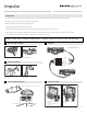
1 LED (function indication)
2 Cable connector
3 Sensitivity potentiometer
4 Adjustable horn antenna
Digital lter o, normal
setting, maximum
sensitivity.
Digital lter on, when
ltering of vibration
and/or reective
surfaces is necessary.
Detection will be
less sensitive, requiring
more motion to activate
the Impulse
Function switch
OFF*
ON
On
Off
min.
min.
0.5s
max.
4s
max.
Sensitivity
Function switch
Output hold time
* factory setting
5 Internal side panels (aps)
6 Function switch
7 Output hold time potentiometer
1
2
3
4
5
6
7
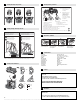
Motion detection (Adjustment of relay hold time potentiometer):
•
Set potentiometer between 7-8 o'clock to get
a xed hold time of 0.5 s and a velocity of 2” (5 cm) / s
• Set potentiometer between 9-5 o'clock to get
a hold time of 0.5 s @ 9 o’clock to 4 s @ 5 o’clock, with a velocity of 4” (10 cm) / s
10
9
3 Steps
4 Steps
9 Steps
Factory setting
Top
view
0 point
15˚
20˚
30˚
45˚
+1 Step
5˚
min.
15˚
max.
45˚
Value for mounting height of 7' 3" (2.2 m) . Maximum mounting height: 13' 1" (4 m).
Avoid rain exposure
Avoid moving objects
in sensing field
Avoid vibrations
Avoid proximity to
fluorescent lights
If after troubleshooting a problem, a satisfactory solution cannot be achieved,
please call
Bircher Reglomat at 800 - 252-1272
from 8am - 5pm central standard time.
You may also visit our website at www.bircherreglomat.com
DO NOT LEAVE ANY PROBLEMS UNRESOLVED
NEVER SACRIFICE SAFETY FOR ANY REASON
Technical data
2
Contact
Bircher Reglomat reserves the right to change any information on this document
without notice.
For the latest version, please log on to www.bircherreglomat.com
or call us at 847-952-3730 to request a copy of the current version.
Disclaimer
K6202.029 08/06 Bircher Reglomat reserves the right to change any information on this document without notice.
Power supply
Current consumption
Temp. range
Humidity
Microwave module
Transmitting power
Relay output pot. free
Switching voltage
Switching current
Switching power
Protection class
Housing material
6
Fig. 6.1 Fig. 6.2 Fig. 6.3
Open position / narrow eld
Closed position / wide eld
Side position / side eld
8
11
12
13
Adjustable antenna
Closed position (see g.6.2)
Min.
Max.
Minimum
eld
dimensions
4' 11" x 3' 3" (1.5 x 1.0 m)
Sensitivity potentiometer
Maximum
eld
dimensions
11' 6" x 6' 7" ( 3.5 x 2.0 m)
Adjustable antenna
Open position (see g. 6.1)
Min.
Max.
Minimum
eld
dimensions
3’ 3" x 1' 8" (1.0 x 0.5 m)
Sensitivity potentiometer
Maximum
eld
dimensions
8' 2" x 8' 2" (2.5 x 2.5 m)
Interference avoidance
Setting all other parameters
Setting frontal inclination
Setting sensing field shape and size
Setting field shape and position
12-28 V AC / 12-36 V DC
approx. 100 mA at 24 V AC,
+20° C
-4 °F to +140 °F [
-20° C to +60° C]
0 to 90%, non condensing
K-band 24,125 GHz +/ 100 MHz
≤
20 dBm
change-over contact
48 V AC/DC
0.5 A AC/1 A DC
55 VA / 24 W
suitable for the application after IP 54
ABS