
User's Manual
61-89A-50-A18-G1-UserMan page 5 of 20
TX RX Systems Inc. Manual 7-9352 (version 4) 01/27/04 Page 5
Table of Contents
Specifications 6
General Description 6
Note About Output Power Rating 8
Installation 8
Cautionary Note 8
Pre-RF Connection Tests 9
Test Equipment 9
Antenna Isolation 9
Procedure for Measuring Antenna Isolation 10
Increasing Isolation 10
Input Signal Levels 10
Procedure for Measuring Input Signal Levels 13
Reduction of Incoming Signal Strength 13
Operation 13
Main Status Display Screen 13
Configuration Settings 14
Calibrate Currents 14
Set Gain 14
Set Output Level 14
Detailed Status Screens 14
Amplifiers 14
Power Supply 14
OLC 14
OLC Historical Info 14
Alarms 14
LED Indicators 14
Form-C Contacts 15
Performance Survey 15
Maintenance and Repair 17
illustrations & Tables
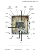
Figure 1 Front view of the Model 61-89A-50-A18-G1 7
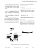
Figure 2 Measuring Antenna Isolation 9
Figure 3 Measuring Input Signal Levels 11
Figure 4 Software flow chart 12
Figure 5 Boot-up display screen 13
Figure 6 Main status display screen 13
Figure 7 Measuring Signal Booster Gain 15
Figure 8 Surveying Performance 16