
User's Manual

61-89A-50-A18-G1-UserMan page 6 of 20
TX RX Systems Inc. Manual 7-9352 (version 4) 01/27/04 Page 6
GENERAL DESCRIPTION
Signal boosters extend radio coverage into areas
where abrupt propagation losses prevent reliable
communication. This system receives an RF sig-
nal, raises its power level, and couples it to an
antenna or leaky (radiating) coaxial cable system
so that it can be re-radiated. No frequency transla-
tion (conversion) occurs with this device.
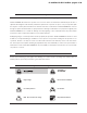
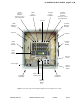
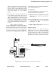
The two-way signal booster model 61-89A-50-A18-
G1 (shown in
Figure 1
) is a broadband, bidirec-
tional dual branch (uplink and downlink) system
with an 18 MHz passband. The booster passes
uplink signals from 806 to 824 MHz and downlink
signals from 851 to 869 MHz. Linear RF active
amplifiers, filters, and DC power sources are used
to adequately boost and re-radiate the passband
signals.
The system is hardware configurable to operate at
one of two coarse gain levels including medium
(+60 dB gain max) or high (+80 dB gain max). The
coarse gain adjustments is made by physically
removing the low level amplifier card (part# 3-
19575) from the branch. Without the low level card
in place the system gain will be +60 dB max. The
coarse gain of the uplink or downlink branch can be
adjusted independently of each others. In addition,
for fine adjustment the gain of a branch can be
reduced up to 30 dB in 0.5 dB increments via soft-
ware interface regardless of which coarse gain set-
ting the branch is configured for.
The output level of any signal passing through a
signal booster is determined by the systems gain
specification. All signals passing through a prop-
erly operating signal booster are amplified by the
same amount but will come out at power levels that
are related to their respective input level by the
gain specification. Signal leveling is not an
intended function of a signal booster. Amplifier
stages used in this signal booster system may be
damaged by excessively strong input signal levels.
The system is equipped with Output Leveling Cir-
cuitry (OLC) to protect the amplifiers and reduce
spurious signals. It is interesting to note that the
total power for the multicarrier condition is always
less than the maximum single carrier rating. As the
number of carriers increases, the difference
between the single carrier maximum and the total
power of all carriers grows even greater.
Linear power amplifiers (Class-A or Class-AB oper-
ation) are used in this application in contrast to the
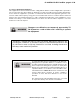
Ele c t r ica l
Frequency Range: 806-869 MHz
FCC Identification Number: EZZ5PI031202
Number of Passbands: 2
Passband Frequencies: 806-824 / 851-869 MHz
Minimum Passband Separation: 45 MHz
Pass Bandw idth: 18 MHz
Gain: +80 dB
Guardband: 27 MHz
Output Level Control Range: 60 dB (less user programmed digital attenuation)
System Noise Figure at Maximum Gain: 3.5 dB maximum
Pow er Output 806-824 MHz ((total composite) 1.3 Watts
Pow er Output 851-869 MHz (total composite) 1.6 Watts
Third Order Output Intercept Point: +55 dBm minimum, w ith no attenuation
Primary Supply Voltage: 100-240 VAC; 50-60 Hz
Automatic Battery Backup Option: +24 to +30 VDC
M e chanical
Height: 24"
Width: 24"
Depth: 8"
Weight 85 lbs.
Housing Type: Painted Steel
Enclosure Type: NEMA 4 Standard
Model 61-89A-50-A18-G1 Specifications