
User's Manual
61-89A-50-A18-G1-UserMan page 8 of 20
TX RX Systems Inc. Manual 7-9352 (version 4) 01/27/04 Page 8
highly efficient Class-C power amplifiers used in
the output stages of most FM land mobile transmit-
ters. Linear amplifiers are biased for a relatively
high continuous DC current drain. Class-A amplifi-
ers generally have the lowest efficiency of the vari-
ous amplifier types, typically in the range of 25 -
33% and Class-AB amplifiers can reach 50% effi-
ciency. Their biggest advantage is faithful repro-
duction of the input waveform which results in the
lowest levels of intermodulation distortion products
(IM) of all the classes of amplifiers. The generation
of IM distortion is a serious design consideration
when two or more channels are simultaneously
present in the same amplifier stage.
Filtering is used at the input and output of the sig-
nal path to help suppress any IM products that may
be inadvertently generated. Signals that exceed
the maximum input rating may either damage the
signal booster or cause it to generate intermodula-
tion products that exceed the maximum allowed by
the FCC or other regulatory agency.
Note About Output Power Ratings
A single maximum output power rating does not
apply to broadband signal boosters because the
linear amplifiers used in them may have to process
multiple simultaneous signals. Under these condi-
tions, the questions of power rating becomes more
complex.
When more than one signal is amplified, a number
of spurious signals will also appear in the amplified
output. They are referred to as intermodulation dis-
tortion products, more commonly called IM. These
spurious products would not be present in a per-
fectly linear amplifier but as in all things, something
short of perfection is realized. Accepted industry
practice is to use the Third Order Intercept Point
specification of a signal booster to predict the level
of IM products. The intercept point is derived from
the measurement of an amplifiers 1 dB compres-
sion point.
INSTALLATION
The layout of the signal distribution system will be
the prime factor in determining the mounting loca-
tion of the signal booster enclosure. However,
safety and serviceability are also key consider-
ations. The unit should be located where it cannot
be tampered with by unauthorized personnel yet is
easily accessible to service personnel using trou-
ble shooting test equipment such as digital multim-
eters and spectrum analyzers. Also consider the
weight and size of the unit should it become
detached from its mounting surfaces for any rea-
son.
Very little is required to install this signal booster.
The unit should be bolted in its permanent position
using lag bolts or other suitable fasteners. Make
sure there is an unobstructed airflow over the
external heatsinks. Safety and serviceability are
key considerations. The signal booster cabinet will
stay warm during normal operation so in the inter-
est of equipment longevity, avoid locations that will
expose the cabinet to direct sun or areas where the
temperature is continually elevated.
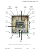
Connection of RF to the unit is made via “N” female
connectors located on bottom of the cabinet.
These connectors are individually labeled “Down-
link In / Uplink Out” and “Downlink Out / Uplink In”.
Care should be used when making connections to
these ports to insure the correct antenna cable is
connected to its corresponding input / output port
or the system will not work. The use of high quality
connectors with gold center pins is advised. Flexi-
ble jumper cables made of high quality coax are
also acceptable for connecting to rigid cable sec-
tions.
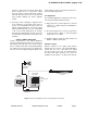
The signal booster is designed to be powered from
120 VAC and a conduit entry box is provided at the
bottom of the enclosure for bringing the AC line into
the cabinet. AC line connections should be made in
accordance with local electrical and building codes.
In addition, the unit is capable of being operated
from a backup DC power source between +24 and
+30 VDC. A terminal screw connector is available
inside the bottom of the cabinet for connecting the
backup voltage. In addition, there are also terminal
screw connections inside the cabinet for alarm
monitoring that are designed for connection to a
customer supplied supervisory alarm system, see
figure 1.
CAUTIONARY NOTE
The following cautions are not intended to frighten
the user but have been added to make you aware
of and help you to avoid the areas where experi-
ence has shown us that trouble can occur.
1) Just like the feedback squeal that can occur
when the microphone and speaker get too close
to each other in a public address system, a sig-
nal booster can start to self oscillate. This will
occur when the isolation between the input