
User's Manual


Manual 7-9386-1 Page 16TX RX Systems Inc. 09/30/04
61-68-50 UserMan page 16 of 25
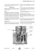
LCD Screen
Once the boot-up sequence is completed (after
several seconds) the LCD screen will switch to the
main status display as shown in figure 6. This is the
normal display for the signal booster. The system
will return to this display from any other display if
none of the menu interface buttons are pressed
within 2 minutes. The exception is the OLC status
display which does require a button press to exit.
The main status display shows the uplink and
downlink gain in dB as well as the uplink and down-
link output level in dBm.
The last line of the main status display gives a
summary status message for the entire signal
booster. In this example “Status OK” is being dis-
played. Pressing the “ENTER” button will move you
from the main status display into the menu selec-
tions and will permit interaction with the system.
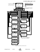
There are two main functions available within the
software menus including configuration settings
and detailed status displays.
Configuration Settings
In most cases, the factory default settings are the
optimum values for adjustable parameters. The
most common setting to be changed by the sys-
tem’s technician is the gain setting. This is normally
done to compensate for varying values of antenna
isolation as outlined earlier in this manual or to
reduce excessive OLC action resulting from exces-
sive gain.
Please thoroughly study this section before making
any adjustments to the configuration values. Each
configured item is discussed in detail.
Note:
Changes to configuration set-
tings do not take affect until the Main
Status screen is re-enabled. This
occurs automatically after 2 minutes
without button input or manually by
pressing the Enter/Done/Cancel buttons to return
to the status screen.
RESTORE ORIG CONFIG
This command will restore all configured settings to
their original factory default values. SB II ships from
the factory preset to the lowest gain possible.
CALIBRATE CURRENTS
Use this command when replacing an RF amplifier.
This function automatically calibrates the current
alarm “trip” point of each amplifier in the system.
Due to manufacturing tolerances there are small
differences in current draw between amplifier
assemblies. This software function matches the
alarm sensing circuit to the respective amplifier
assembly and should be repeated whenever an
amplifier assembly is replaced.
SET GAIN
This function allows the user to electronically set
the gain of the booster in 0.5 dB increments over a
range of 30 dB. Gain can be adjusted indepen-
dently for both the uplink and downlink channels
but in most cases both uplink and downlink should
be set to the same gain value.
Know your antenna isolation before making this
adjustment. We recommend that you temporarily
disconnect both the uplink and downlink antennas
when setting the gain to avoid the possibility of
causing the unit to oscillate. After changing the set-
ting, power the unit down, reconnect the antennas
and power-up the booster.
Note:
A reduction in system gain will
also result in an equal reduction in the
OLC dynamic range, refer to the sec-
tion titled “OLC” on page 11.
SET OUTPUT LEVEL
Allows the output power for the uplink and downlink
channels to be independently adjusted in 0.5 dB
increments up to +31 dBm. Note that the OLC cir-
cuitry will maintain the systems output level at the
values you have selected in this menu.
Use this function ONLY if your system is causing
some form of interference to another radio system.
You can only reduce the booster’s output power
with this command.
CHANGE GAIN CONFIGURATION
Insures proper gain readings when changing basic
booster gain by changing the type of plug-in card
assemblies.
Use of this menu is ONLY needed when converting
your stock SB II to a different gain level by chang-
ing the low level, mid-level plug-in amplifier card or
the addition of an attenuator card. The addition of
these cards will change the unit to another model
within the UHF SB II family, see table 2. Don’t con-
fuse this with simple amplifier bypassing to reduce
gain. Uplink and down link can be set indepen-
NOTE
NOTE