
User's Manual
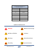
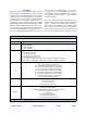
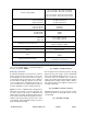

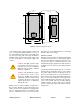
Table Of Contents

TX RX Systems Inc. Manual 7-9485-1.9.1 10/26/17 Page 10
correct branch of the antenna system is connected
to its corresponding uplink/downlink connector or
the system will not work properly. Using high qual-
ity connectors with gold center pins is advised.
Flexible jumper cables made of high quality coax
are also acceptable for connecting to rigid cable
sections.
Caution: The ERP (effective radi-
ated power) from the booster sys-
tem must not exceed +37 dBm (5
Watts) in order to remain compliant
with FCC regulations.
Caution: The maximum continu-
ous input power level for this
booster is -20 dBm. Stronger input
signals will cause the unit to exceed
it’s IM specifications. Static input
signals greater than -10 dBm may
damage the unit.
Models of the booster are available for either AC or
DC operation. Based on the model number (see
table 1) the booster is designed to be plugged into
either a single phase AC line (110 VAC at 50/60
Hz) or a - 48 Volt DC source. A connector is avail-
able at the top of the equipment box for connecting
the AC or DC source voltage.
Antenna Isolation
Antenna isolation between uplink and downlink
should be measured before connecting the signal
booster to the antenna system. This step is neces-
sary to insure that no conditions exist that could
possibly damage the signal booster and should not
be skipped for even the most thoroughly designed
system.
Just like the feedback squeal that can occur when
the microphone and speaker get too close together
in a public address system, a signal booster can
start to self oscillate. This can occur when the iso-
lation between the Uplink and Downlink antennas
does not exceed the signal boosters gain by at
least 15 dB. Oscillation will reduce the effective-
ness of the system and may possibly damage
amplifier stages. Isolation values are relatively
easy to measure with a spectrum analyzer and sig-
nal generator.
0.44 Dia
(2 places)
0.44 wide slot (2 places)
33.2430.00
14.00 10.8
20.00
Mounting Tabs
(4 Places)
Figure 2: Cabinet mounting hole layout.