
User's Manual
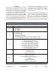
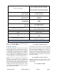

Table Of Contents

TX RX Systems Inc. Manual 7-9485-1.9.1 10/26/17 Page 7
OVERVIEW
Signal boosters extend radio coverage into areas
where abrupt propagation losses prevent reliable
communication. The system receives an RF signal,
raises its power level, and couples it to an antenna
so that it can be re-radiated. The TXRX model
6138X family of channelized signal boosters is
designed to operate in either the 700 or 800 MHz
range. Dual band models are available that include
both 700 and 800 MHz systems in the same enclo-
sure box. The system is based on a module design
with each module capable of handling 14 or 30 car-
riers in the uplink and downlink direction. The sig-
nal booster is available in a variety of
configurations as shown in Table 1. The product
model number is used to describe each configura-
tion available. Model number nomenclature is
described in table 1.
The size of the system can be tailored to the cus-
tomers needs by increasing or decreasing the
number of carriers used. Each module is bi-direc-
tional with one downlink and one uplink signal
branch. Each of the two branches in a module are
independently tunable to their required pass fre-
quencies via software interface. System specifica-
6138X-XX-YY-UD-Z-Options (nomenclature breakdown)
6138X Designates product as 700 - 800 MHz channelized signal booster
XX
Designates operating frequency band
9A = 806 - 869 MHz
3B = 763 - 805 MHz
3G = 763 - 869 MHz
YY
Designates how many modules used and number of filters available
A = 1 module with 14 filters
B = 1 module with 30 filters
AA = 2 modules with 14 filters each
BB = 2 modules with 30 filters each
AB = 1 module (700 MHz) with 14 filters and 1 module (800 MHz) with 30 filters
BA = 1 module (700 MHz) with 30 filters and 1 module (800 MHz) with 14 filters
UD
Designates the type of output for the uplink and downlink
HH = high power uplink and downlink
HL = high power uplink and low power downlink
LH = low power uplink and high power downlink
LL = low power for both uplink and downlink
FH = fiber output uplink and high power downlink
FL = fiber output uplink and low power downlink
HF = high power uplink and fiber output downlink
LF = low power uplink and fiber output downlink
FF = fiber uplink and fiber downlink
Z
Designates mounting style
RM = 19” rack mount
G1 = Painted enclosure
G2 = Stainless steel enclosure
Options
Designates the options that have been added
Blank = no options added
N = NFPA compliant (National Fire Protection Association)
P = 10 MHz high precision reference
D = -48 VDC
Q = Fiber input downlink only
R = Fiber input uplink only
S = Fiber input downlink and uplink
Table 1: Model number nomenclature.