
User's Manual
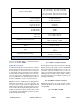

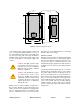
Table Of Contents

TX RX Systems Inc. Manual 7-9485-1.9.1 10/26/17 Page 9
The implication of equation (3) is that the frequency
stability of the signal that is processed by this type
of signal booster is not affected by the frequency
stability of the signal booster itself. Frequency sta-
bility depends only on the stability of the signal
source producing the signal to be boosted. A shift
in the LO frequency will cause the center of the fil-
ter bandwidth to move with respect to the signal.
For very narrow filter widths, the channel modules
LO may be locked to a high stability 10 MHz refer-
ence.
UNPACKING
It is important to report any visible damage to the
shipping company immediately. It is the customers
responsibility to file damage claims with the ship-
ping company within a short period of time (1 to 5
days). Care should be taken when removing the
unit from the packing box to avoid damage to the
unit.
INSTALLATION
The following sub-sections of the manual discuss
general considerations for installing the booster. All
work should be performed by qualified personnel
and in accordance with local codes.
Location
The layout of the signal distribution system will be
the prime factor in determining the mounting loca-
tion of this unit. However, safety and serviceability
are also key considerations. The unit should be
located where it can not be tampered with by the
general public, yet is easily accessible to service
personnel. Also, consider the weight of the unit and
the possibility for injury if it should become
detached from its mounting for any reason.
The booster needs to be installed such that there
can be unobstructed air flow around the equip-
ment. Insure that the heat sink fins are unob-
structed. The various subassemblies within the
equipment cabinet will stay warm during normal
operation so in the interest of equipment longevity,
avoid installation locations that carry hot exhaust
air or are continually hot.
Mounting
Figure 2 shows the mounting hole dimensions and
layout for the cabinet. Mount the cabinet using 3/8”
(10 MM) diameter steel bolts (not supplied). We
recommend flat washers on both ends and a lock
washer under the nut. Nut and bolt mounting is
preferred to the use of lag bolts. Use backer blocks
where necessary to spread the force over a larger
area. In areas of known seismic activity, additional
devices such as tether lines may be necessary.
Because Bird Technologies cannot anticipate all of
the possible mounting locations and the structure
types where these devices will be located, we rec-
ommend consulting local building inspectors, engi-
neering consultants or architects for advice on how
to properly mount objects of this type, size and
weight in your particular situation. It is the custom-
ers responsibility to make sure that these devices
are mounted safely and in compliance with building
codes.
Connections
All RF cabling connections to the booster should
be made and checked for correctness prior to pow-
ering up the system. N(f) bulkhead connectors are
available at the top of the booster enclosure box for
connection to the system antennas. Make sure the
Intermediate
Frequency
Signal
Processing
1st Mixer 2nd Mixer
RF OutRF In
Local
Oscillator
Figure 1: The down converter / up converter process.