
Operation Manual
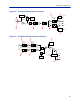
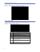
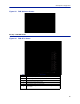
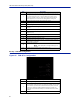
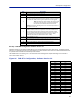
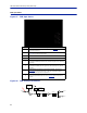
Table Of Contents
- Safety Precautions
- About This Manual
- Table of Contents
- Chapter 1 Introduction
- Chapter 2 System Description
- Chapter 3 Installation guidelines
- Chapter 4 DAS Software Configuration
- Chapter 5 Commissioning
- Chapter 6 RF Commissioning
- Chapter 7 Troubleshooting
- Alarms
- Base Station Gateway (BGW) Alarms
- Fiber Optic Remote (FOR) Alarms
- Remote Unit (RU) Alarms
- Fiber optic Interface (FOI) Alarms
- Base Station Interface (BIU) Alarms
- Medium Power Amplifier (PA) Alarms
- Variable Gain Amplifier (VGA) Alarms
- Analog Pre-distortion (APD) Amplifier Alarms
- Multi-carrier Power Amplifier Interface (MPI) alarms
- Alarms
- Chapter 8 Model Identification

Fiber Distributed Antenna System (Fiber DAS)
89
FOR Opto Status
Figure 97 FOR Opto Status
1
2
3
4
5
6
7
8
Item Description
1
Optical power received from the FOI. See item 1 in
Figure 98
for
measurement location.
2
Uplink signal being fed into the FOR uplink laser circuit. See item 2 in
Figure 99
for measurement location.
3 Laser current for the Remote Unit FOR. Should be less than 50mA.
4 Temperature of the Remote Unit FOR board.
5
Total gain of the FOR in the downlink. Note that RF Out 1 and 2 are wide
band (FM to 2600MHz) that feed band specific RF amplifiers in the following
VGA stage.
6
Total gain of the FOR in the uplink path. Note that RF In1 and In2 are wide
band (FM to 2600MHz) that are signals from the uplink frequency specific
amplifiers.
7
Calculated downlink signal being received from the FOI. See item 1 in
Figure 98
for measurement location. Takes into consideration optical
wavelength and temperature compensation.
8
Calculated uplink signal being transmitted to the FOI (FOR input from VGA +
FOR uplink gain/attenuation). See item 3 in
Figure 99
for measurement
location.
Figure 98 FOR Downlink Schematic
CURRENT
SENSOR
ETHERNET
MODEM
OPTO IN
RX-LVL
RF OUT 1
RF OUT 2
PHOTO
DETECTOR
STEP ATT STEP ATT
1