
Operation Manual
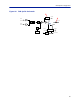
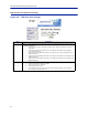


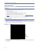
Table Of Contents
- Safety Precautions
- About This Manual
- Table of Contents
- Chapter 1 Introduction
- Chapter 2 System Description
- Chapter 3 Installation guidelines
- Chapter 4 DAS Software Configuration
- Chapter 5 Commissioning
- Chapter 6 RF Commissioning
- Chapter 7 Troubleshooting
- Alarms
- Base Station Gateway (BGW) Alarms
- Fiber Optic Remote (FOR) Alarms
- Remote Unit (RU) Alarms
- Fiber optic Interface (FOI) Alarms
- Base Station Interface (BIU) Alarms
- Medium Power Amplifier (PA) Alarms
- Variable Gain Amplifier (VGA) Alarms
- Analog Pre-distortion (APD) Amplifier Alarms
- Multi-carrier Power Amplifier Interface (MPI) alarms
- Alarms
- Chapter 8 Model Identification

Fiber Distributed Antenna System (Fiber DAS)
91
FOR Opto Gain and Attenuation Settings
Figure 100
1
2
FOR Opto Gain Settings
Item Description
1
FOR gain in the downlink path. Range is typically from -20 to +20. FOR downlink path has inherent/raw gain of
+20dB (FM to 2600MHz).
A setting of +20 indicates no attenuation so FOR will have +20dB gain (+20dB gain minus 0dB
attenuation).
A setting of +10 will have 10 of attenuation so this stage will have 10dBm of gain (+20dB gain
minus 10dB of attenuation).
A setting of 0 will have 20dB of attenuation so this stage will have unity gain (+20dB gain minus
20dB of attenuation).
A setting of -10 will have 30dB of attenuation so this stage will have 10dB of loss (+20dB gain minus
30dB of attenuation).
A setting of -20 will have 40dB of attenuation so this stage will have 20dB of loss (+20dB gain minus
40dB of attenuation).
2
FOR gain in the uplink path. Range is typically from 0 to +20dBm (FM to 2600MHz).
A setting of +20 will have full gain of +20dBm.
A setting of +10 will have +10dB gain.
A setting of 0 will have no gain.
Factory default should be used unless high loss in fiber. Note that changes in Gain uplink will
require changes in the FOR UL ALC level.