
Operation Manual
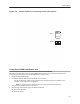
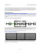
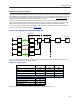
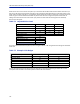
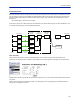
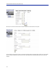
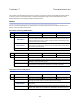
Table Of Contents
- Safety Precautions
- About This Manual
- Table of Contents
- Chapter 1 Introduction
- Chapter 2 System Description
- Chapter 3 Installation guidelines
- Chapter 4 DAS Software Configuration
- Chapter 5 Commissioning
- Chapter 6 RF Commissioning
- Chapter 7 Troubleshooting
- Alarms
- Base Station Gateway (BGW) Alarms
- Fiber Optic Remote (FOR) Alarms
- Remote Unit (RU) Alarms
- Fiber optic Interface (FOI) Alarms
- Base Station Interface (BIU) Alarms
- Medium Power Amplifier (PA) Alarms
- Variable Gain Amplifier (VGA) Alarms
- Analog Pre-distortion (APD) Amplifier Alarms
- Multi-carrier Power Amplifier Interface (MPI) alarms
- Alarms
- Chapter 8 Model Identification

RF Commissioning
114
Noise load on Radio Base Station
The system will inevitably add some noise to the receiver. When properly set up the noise figure in a system like this
will be better than 3 dB. However, if the gain is improperly set up (i.e. not enough gain in the remote, too much gain
in the head-end) it is possible to create a very bad noise figure. In order to avoid this the Fiber-DAS Calculator
should be used to calculate the noise figure of the system in the uplink.
If you have not familiarized yourself with the Fiber-DAS Calculator, do so before moving on in this manual. The
figures in the Fiber-DAS calculator relate to the settings of all steps in the chain. By using the calculator, you can
determine the proper settings once you know the fiber loss between the Remote Unit and the headend.
Let us assume you’ve arrived at a Noise Figure (NF) of 3 dB for this chain. How
ever your system may contain more
remotes, perhaps connected like the system in
Figure 136
.
Figure 136
!
Multiple RU Connection Diagram
Now the noise load can be calculated by adding the noise contribution from each step of the chain. Below is an
example of noise figures from each of the remotes:
Table 73
Chain NF Gain Noise Load
RU 1
2.8 0.0 2.8
RU 2
3.2 1.0 4.2
RU 3
3.8 -2.0 1.8
RU 4
2.6 -1.0 1.6
Sum of Noise Load 8.7
Base Station
4.0
Fiber-DAS Noise Load
8.0
Total Noise into BTS
9.5
Desensitization -5.5
Noise Load
Add your figures to the sheet in the Fiber-DAS calculator and it will calculate it for you.