
Operation Manual
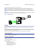
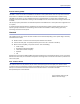
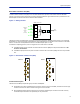
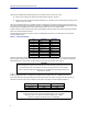
Table Of Contents
- Safety Precautions
- About This Manual
- Table of Contents
- Chapter 1 Introduction
- Chapter 2 System Description
- Chapter 3 Installation guidelines
- Chapter 4 DAS Software Configuration
- Chapter 5 Commissioning
- Chapter 6 RF Commissioning
- Chapter 7 Troubleshooting
- Alarms
- Base Station Gateway (BGW) Alarms
- Fiber Optic Remote (FOR) Alarms
- Remote Unit (RU) Alarms
- Fiber optic Interface (FOI) Alarms
- Base Station Interface (BIU) Alarms
- Medium Power Amplifier (PA) Alarms
- Variable Gain Amplifier (VGA) Alarms
- Analog Pre-distortion (APD) Amplifier Alarms
- Multi-carrier Power Amplifier Interface (MPI) alarms
- Alarms
- Chapter 8 Model Identification

System Description
6
Remote Gateway (RGW)
The RGW is a small unit similar to the BGW but intended for small systems where there are only a few remotes or
where there is no headend. The RGW has a form factor that allows it to be mounted inside a repeater casing.
The RGW can be used to run up to 4 Remote Units from a single Repeater on a single Fiber. The RGW has the
capability to connect northbound to a CGW, just like the BGW, and it can also forward alarms through a VPN tunnel
to a CGW.
The memory capacity and features are reduced c
ompared to the BGW but for a small system with a single fiber this
is an option.
In remote locations without Ethernet, the RGW can be equipped with a modem to allo
w remote access to the
system. Typically a 3G modem is used allowing a VPN tunnel from the RGW to a CGW, enabling supervision,
monitoring and control of the system.
Headend
The headend consists of a 19-inch rack with modules that are selected depending on the system design. Generally
all headend Units contain:
Network switch - connects communication paths between the modules
Interconnect Unit (ICU) - RF splitter/combiner (rack-mount unit or module in the MFU)
Master Frame Unit (MFU), may contain some or all of the following:
Power supply
Base Station Interface Unit (BIU)
Fiber-Optic Interface card (FOI)
Repeater
ICU
A DHCP server built into the RGW and BGW will assign IP addresses to all the headend subunits in the rack and the
Remote Units when they are connected to the system. The configuration is automatic and creates a protected sub-
net for the system.
DCS - Network Switch
The network switch is an AC powered, 24-port switch with Spanning Tree Protocol (STP). The network switch
provides an Ethernet link between the MFU and the BGW. Each card slot in the MFU has a dedicated Ethernet port,
each port is connected to the network switch and the network switch is connected to the BGW.
A DC powered option is also available.
Actual network switch may be
different from the image.