
Operation Manual
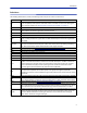
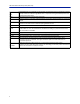
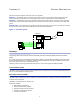
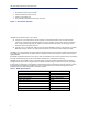
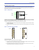
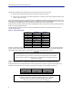
Table Of Contents
- Safety Precautions
- About This Manual
- Table of Contents
- Chapter 1 Introduction
- Chapter 2 System Description
- Chapter 3 Installation guidelines
- Chapter 4 DAS Software Configuration
- Chapter 5 Commissioning
- Chapter 6 RF Commissioning
- Chapter 7 Troubleshooting
- Alarms
- Base Station Gateway (BGW) Alarms
- Fiber Optic Remote (FOR) Alarms
- Remote Unit (RU) Alarms
- Fiber optic Interface (FOI) Alarms
- Base Station Interface (BIU) Alarms
- Medium Power Amplifier (PA) Alarms
- Variable Gain Amplifier (VGA) Alarms
- Analog Pre-distortion (APD) Amplifier Alarms
- Multi-carrier Power Amplifier Interface (MPI) alarms
- Alarms
- Chapter 8 Model Identification

System Description
8
Base Station Interface Unit (BIU)
The Base Station Interface Unit (BIU) is the interface between the operator’s base station and the Fiber-DAS
system. The primary purpose of the BIU is to adjust uplink and downlink signal levels.The BIU is powered from the
MFU backplane and communicates via Ethernet with the BGW.
Figure 4 BIU Signal Flow
Base
Station
Base Station
Interface
Interconnect
Unit
Fiber-Optic
Interface Units
Fiber-Optic
Cables
to
Remote
Units
(Antenna)
Master Frame Unit
FOI
FOI
FOI
FOI
ICU
BIU
The BIU has uplink and downlink RF connectors on the front panel and is available in two variants, one containing
duplex filters or one with separate uplink/downlink paths, depending on the needs for the connection to the base
station. In most cases the duplexed version with a combined DL/UL ports is used.
In addition to duplexing options, there is a single slot and a dual version of the BIU:
The DBI3xx (wide version) includes an external alarm connector (DB9) and requires two MFU slots. This
version is now obsolete.
The DBI3xxC (compact version) does not have an external alarm connector (DB9), and uses only one MFU
slot.
Figure 5
BIU
ALM
ON
DL/UL BTS 1
TP UL 1
TP UL 2
DL OUT 1
UL IN 1
DL OUT 2
UL IN 2
DL/UL BTS 2
BIU
ALM
ON
DL/UL BTS 1
TP UL 1
EXTERNAL
ALARM
TP UL 2
DL OUT 1
UL IN 1
DL OUT 2
UL IN 2
DL/UL BTS 2
DBI3xxC
DBI3xx
Base Station Interface Unit (BIU)
Functional description
The BIU has four SMA ports (female type) to connect the RBS/BTS.
Duplexed versions have combined DL/UL connectors used to connect to the RBS, and there are UL test (TP)
connectors that can be used to monitor the signal out from the BIU.
Non-duplexed (simplex) versions have the test connectors replaced by UL connectors and the normally
combined UL/DL connectors are replaced by DL only connectors.