
Operation Manual
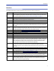
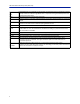
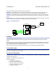
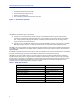
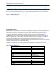
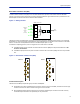
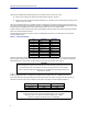
Table Of Contents
- Safety Precautions
- About This Manual
- Table of Contents
- Chapter 1 Introduction
- Chapter 2 System Description
- Chapter 3 Installation guidelines
- Chapter 4 DAS Software Configuration
- Chapter 5 Commissioning
- Chapter 6 RF Commissioning
- Chapter 7 Troubleshooting
- Alarms
- Base Station Gateway (BGW) Alarms
- Fiber Optic Remote (FOR) Alarms
- Remote Unit (RU) Alarms
- Fiber optic Interface (FOI) Alarms
- Base Station Interface (BIU) Alarms
- Medium Power Amplifier (PA) Alarms
- Variable Gain Amplifier (VGA) Alarms
- Analog Pre-distortion (APD) Amplifier Alarms
- Multi-carrier Power Amplifier Interface (MPI) alarms
- Alarms
- Chapter 8 Model Identification

Fiber Distributed Antenna System (Fiber DAS)
9
The BIU has four QMA ports (female type) that are normally used to connect it to an ICU.
There are two uplink (input, RX) ports and two downlink (output, TX) ports.
These are two separate paths, the isolation between DL 1 and DL 2 ports and the isolation between the UL
1 and UL 2 ports is > 50 dB.
There are two separate RF paths in the BIU. The BIU is configured for the specific frequency band it will serve. The
two paths in the BIU cannot have different frequencies; a 900 MHz BIU will have two 900 MHz paths and cannot be
combined with an 1800 MHz path. Separate frequencies require the use of an additional BIU.
RF patch cables are used to patch the DL and UL paths (QMA) to the ICU.
The RF patch cables high quality, low PIM
cables such as Bird’s DCC320 cable set.
The DBI 3xx (dual slot) BIU has an alarm output port (DB9 female connect
or) on the BIU which can be used to
connect external alarms.
Table 3 Alarm Port Pinout
Pin Signal (A) Signal (B)
1 RS485+ RS485+
2 Alarm out 1 Alarm out 1
3 Ground Ground
4 Not connected Alarm in 2
5 Not connected Alarm in 4
6 RS485+ RS485+
7 Alarm out 2 Alarm out 2
8 G Alarm in 3
9 Not connected Alarm in 1
The BIU is technology neutral and the downlink path contains settable attenuators that can be used to adjust the
signal strength to proper levels before feeding them into the ICU. In the uplink there is an amplifier followed by a
settable attenuator used to adjust the signal and the noise level into the base station uplink.
CAUTION
Overdriving the RF source input into the BIU will cause permanent equipment failure and
will void the warranty. The installer must ensure that input levels are not exceeded.
Plan for maximum power out of the RF source and attenuate accordingly with external
attenuators if needed.
All RF connections are made on the front of the BIU. The maximum recommended input power to the BIU is
30 dBm. A high power alarm is activated at > 30 dBm and a low power alarm at < 10 dBm input power.
Input power above the recommended level can cause permanent unit failure. For high power base stations, an
attenuator should be used to ensure that the input power to the BIU can never exceed specifications.
BIU Type Minimum DL Input Maximum DL Input
Low Level -7dBm +13dBm
High Level +20dBm +33dBm
CAUTION
The UL from the FOI card is capable of damaging the UL port on the BIU.
Maximum input to the BIU UL should be no higher than +13dBm.
Use care to properly set FOI levels prior to enabling RF.