
Operation Manual
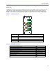
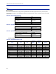
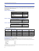
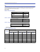
Table Of Contents
- Safety Precautions
- About This Manual
- Table of Contents
- Chapter 1 Introduction
- Chapter 2 System Description
- Chapter 3 Installation guidelines
- Chapter 4 DAS Software Configuration
- Chapter 5 Commissioning
- Chapter 6 RF Commissioning
- Chapter 7 Troubleshooting
- Alarms
- Base Station Gateway (BGW) Alarms
- Fiber Optic Remote (FOR) Alarms
- Remote Unit (RU) Alarms
- Fiber optic Interface (FOI) Alarms
- Base Station Interface (BIU) Alarms
- Medium Power Amplifier (PA) Alarms
- Variable Gain Amplifier (VGA) Alarms
- Analog Pre-distortion (APD) Amplifier Alarms
- Multi-carrier Power Amplifier Interface (MPI) alarms
- Alarms
- Chapter 8 Model Identification

System Description
20
DOI401 FOI
The DOI401 four port FOI is very similar to DOI302 expect that it has four WDM optical ports instead of one. This
allows the user to install dedicated fibers to each Remote Unit without having to balance optical splitter link
budgets for each remote in a group. The balanced splitter loss is accounted for in the 7 dBo link budget of the
DOI401. Unlike the DOI302, the DOI401 does not require the UL optical signals to be on different wavelengths.
Figure 17 DOI401 Interfaces
OPTO IN/OUT 1
OPTO IN/OUT 2
OPTO IN/OUT 3
OPTO IN/OUT 4
FOI
ALM
ON
UL OUT 1
TP DL
RES
TP UL
DL IN 1
DL IN 2
UL OUT 2
Item Description
OPTO IN/OUT SC-APC connections for the optical fiber.
UL OUT 1/2 Uplink ports to the ICU/BIU.
DL IN 1/2 Downlink ports to the ICU/BIU.
TP UL/DL Test ports used to check the signal levels or noise in the system.
Table 15 DOI401 Specifications
Parameter Value
Maximum fiber loss from MU to RU, Optical, 7 dBo
Optical output power, Calibrated 3 000 μW
Maximum number of RU supported on single fiber 1
Input RF power recommended, Composite -50 to -35 dBm
Power consumption < 20 W
Operational Temperature range 0 to 45 °C (32 to 113 °F)
Module Width 2 card slot
Optical connector type SC-APC
RF connector type QMA Female