
Operation Manual
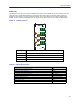
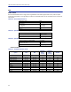
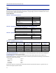
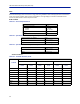
Table Of Contents
- Safety Precautions
- About This Manual
- Table of Contents
- Chapter 1 Introduction
- Chapter 2 System Description
- Chapter 3 Installation guidelines
- Chapter 4 DAS Software Configuration
- Chapter 5 Commissioning
- Chapter 6 RF Commissioning
- Chapter 7 Troubleshooting
- Alarms
- Base Station Gateway (BGW) Alarms
- Fiber Optic Remote (FOR) Alarms
- Remote Unit (RU) Alarms
- Fiber optic Interface (FOI) Alarms
- Base Station Interface (BIU) Alarms
- Medium Power Amplifier (PA) Alarms
- Variable Gain Amplifier (VGA) Alarms
- Analog Pre-distortion (APD) Amplifier Alarms
- Multi-carrier Power Amplifier Interface (MPI) alarms
- Alarms
- Chapter 8 Model Identification

Fiber Distributed Antenna System (Fiber DAS)
21
PSU – the rack power supply
The Power Supply Unit provides DC power to the Master Unit backplane. The unit is shipped as 240 VAC or 115 VAC
units depending on the country. A -48 VDC input is offered as an option.
Figure 18 PSU
AC Power Supply
DC Power Supply
Functional description
The AC power supply can handle up to 16 cards or one chassis full of cards. The DC power supply is capable of
handling 12 cards or one full chassis that includes the DC power supply.
All connectors are on the front side of the power supply.
Figure 18
shows the PSU equipped with European power
inlet.
The PSU outputs are two 10-pin Molex connectors, these are connected to the chassis to supply power. One
connector should always be connected to the chassis holding the PSU (for driving the fans).
One chassis can hold up to 4 power supplies. Two PSU’s may be connected to a chassis to provide redundancy.
Table 16
Parameter Value
Input power voltage, Mains
DPU301
DPU302
86-264 VAC, 50 / 60 Hz
38 - 60 VDC
Operating temperature -25 to 55 °C (32 to 131 °F)
Power rating 240 W
Width 4 card slots
PSU Specifications