
Operation Manual
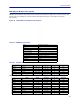


Table Of Contents
- Safety Precautions
- About This Manual
- Table of Contents
- Chapter 1 Introduction
- Chapter 2 System Description
- Chapter 3 Installation guidelines
- Chapter 4 DAS Software Configuration
- Chapter 5 Commissioning
- Chapter 6 RF Commissioning
- Chapter 7 Troubleshooting
- Alarms
- Base Station Gateway (BGW) Alarms
- Fiber Optic Remote (FOR) Alarms
- Remote Unit (RU) Alarms
- Fiber optic Interface (FOI) Alarms
- Base Station Interface (BIU) Alarms
- Medium Power Amplifier (PA) Alarms
- Variable Gain Amplifier (VGA) Alarms
- Analog Pre-distortion (APD) Amplifier Alarms
- Multi-carrier Power Amplifier Interface (MPI) alarms
- Alarms
- Chapter 8 Model Identification

Installation guidelines
48
Power Supply Unit
Bird Technologies offers two different power supplies for the Master Unit: AC (DPU-301) and DC (DPU-302). The
power supply can be located in a Master Unit other than the one it is powering. Each power supply is shipped with
one Molex power supply jumper. If redundant power supplies are required additional power supply jumper(s) will
need to be ordered.
The power supply uses four slots on the Master Unit.
Prior to installing the PSU in the Master Unit chassis the red slide rails must be carefully removed from the
slots that the PSU will occupy.
Figure 31 Slide Rail Removal
PSU DPU-301
The AC DPU-301 power supply has a standard C13 receptacle.
The AC DPU-301 has an input range from 86-264 VAC at 50 or 60 Hz.
Due to site-specific needs on length and varying standards of AC plug types, the AC power cord does not
ship with the equipment. The installation contractor must provide the AC power cord.
The DPU-301 can support a single, fully loaded Master Frame Unit with up to 16 cards (BIU, FOI, ICU). The cards
may be all of one type or a mixture of types.
Figure 32
DPU-301
DPU-302
Power Supply Units