
Operation Manual


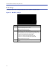
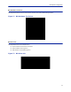

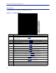
Table Of Contents
- Safety Precautions
- About This Manual
- Table of Contents
- Chapter 1 Introduction
- Chapter 2 System Description
- Chapter 3 Installation guidelines
- Chapter 4 DAS Software Configuration
- Chapter 5 Commissioning
- Chapter 6 RF Commissioning
- Chapter 7 Troubleshooting
- Alarms
- Base Station Gateway (BGW) Alarms
- Fiber Optic Remote (FOR) Alarms
- Remote Unit (RU) Alarms
- Fiber optic Interface (FOI) Alarms
- Base Station Interface (BIU) Alarms
- Medium Power Amplifier (PA) Alarms
- Variable Gain Amplifier (VGA) Alarms
- Analog Pre-distortion (APD) Amplifier Alarms
- Multi-carrier Power Amplifier Interface (MPI) alarms
- Alarms
- Chapter 8 Model Identification

Fiber Distributed Antenna System (Fiber DAS)
71
BIU Configuration
The initial screen for the BIU provides basic information such as name, serial number, part number and active
alarms. The Locate me! button causes an LED to flash on the unit so that the module can be identified in the chassis.
In the left menu, notice the RF 1 and RF 2. The BIU has two RF paths or strips that are correlated to the two RF
inputs on the BIU card. Each RF path has independent settings that can be accessed via the appropriate selection.
Figure 68 BIU Welcome Screen
BIU RF1 Status
This page shows the current status and configuration of the BIU.
Figure 69
1
2
3
4
5
6
7
8
9
10
11
12
13
14
15
BIU RF1 Status