
Operation Manual


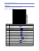
Table Of Contents
- Safety Precautions
- About This Manual
- Table of Contents
- Chapter 1 Introduction
- Chapter 2 System Description
- Chapter 3 Installation guidelines
- Chapter 4 DAS Software Configuration
- Chapter 5 Commissioning
- Chapter 6 RF Commissioning
- Chapter 7 Troubleshooting
- Alarms
- Base Station Gateway (BGW) Alarms
- Fiber Optic Remote (FOR) Alarms
- Remote Unit (RU) Alarms
- Fiber optic Interface (FOI) Alarms
- Base Station Interface (BIU) Alarms
- Medium Power Amplifier (PA) Alarms
- Variable Gain Amplifier (VGA) Alarms
- Analog Pre-distortion (APD) Amplifier Alarms
- Multi-carrier Power Amplifier Interface (MPI) alarms
- Alarms
- Chapter 8 Model Identification

Item Description
1
Downlink RMS value leaving the BIU card to the ICU/FOI. Good for
measuring GSM and UMTS levels.
2 Downlink log detector signal leaving the BIU card to the ICU/FOI.
3 Peak downlink RF value exiting the BIU card on the select path.
4
0=RF is set to Off (attenuation is set to maximum).
1= RF is set to On.
Note: This is only in reference to one of the two BIU RF paths/strips.
5 Temperature of the BIU card.
6
This measurement is the actual loss of the downlink RF signal in the BIU
taking into account raw or inherent loss of the card plus the adjustable
attenuator.
7
This measurement is the actual gain or loss on the uplink RF signal in the BIU
taking into account raw or inherent gain of the card plus the uplink
adjustable attenuator.
8
Adjustable downlink attenuator setting for the selected RF path.
Note: If RF is turned off (see #4) the attenuator value is automatically set to
maximum attenuation. When RF is turned on, the setting of the adjustable
attenuator will be shown.
9
Adjustable uplink attenuator setting for the selected RF path.
Note: If RF is turned off (see #4) the attenuator value is automatically set to
maximum attenuation. When RF is turned on, the setting of the adjustable
attenuator will be shown.
10
Calculated downlink RMS value entering the BIU card from the BTS.
Note: This is the downlink into the BIU card and not an uplink value.
11
Calculated downlink value entering the BIU card from the BTS .
Note: This is the downlink into the BIU card and not an uplink value.
12
Peak downlink RF value entering the BIU card on the select path.
Note: This is the downlink into the BIU card and not an uplink value.
13
0= Downlink alarm is set to Off.
1= Downlink alarm is set to On.
14 Bandwidth of the BIU card
15 Pressing Reload will refresh the page
DAS Software Configuration
72