
Operation Manual


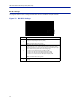
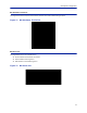

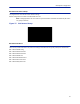
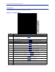
Table Of Contents
- Safety Precautions
- About This Manual
- Table of Contents
- Chapter 1 Introduction
- Chapter 2 System Description
- Chapter 3 Installation guidelines
- Chapter 4 DAS Software Configuration
- Chapter 5 Commissioning
- Chapter 6 RF Commissioning
- Chapter 7 Troubleshooting
- Alarms
- Base Station Gateway (BGW) Alarms
- Fiber Optic Remote (FOR) Alarms
- Remote Unit (RU) Alarms
- Fiber optic Interface (FOI) Alarms
- Base Station Interface (BIU) Alarms
- Medium Power Amplifier (PA) Alarms
- Variable Gain Amplifier (VGA) Alarms
- Analog Pre-distortion (APD) Amplifier Alarms
- Multi-carrier Power Amplifier Interface (MPI) alarms
- Alarms
- Chapter 8 Model Identification

Fiber Distributed Antenna System (Fiber DAS)
79
FOI Opto Status
This page will show the current status and configuration of the FOI.
Figure 80 FOI Opto Status
1
2
3
4
5
6
7
8
9
10
11
12
13
14
16
15
Item Description
1 Fiber optic received optical power from the remote unit. See item 1 in
Figure 81
for measurement location.
2
RF downlink power to the remote. See item 2 in
Figure 82
for location on the FOI circuitry. Note that with no RF
power into the BIU the FOR will still show signal in the downlink. This is the sub-carrier that is typically 10 dB below
the anticipated RF level.
3 RF path 1 input power from the remote. See item 3 in
Figure 81
for location on the FOI circuitry.
4 RF path 2 input power form the remote. See item 4 in
Figure 81
for location on the FOI circuitry.
5 Temperature of the FOI card
6
Downlink path 1 attenuator #1 setting. See item 6 in
Figure 82
for location on the FOI circuitry. Value may be
slightly different than the value in Settings due to changes in temperature compensation.
7
Downlink path 1 attenuator #2 setting. See item 7 in
Figure 82
for location on the FOI circuitry. Value may be
slightly different than the value in Settings due to changes in temperature compensation.
8
Downlink path 2 attenuator #1 setting. See item 8 in
Figure 82
for location on the FOI circuitry. Value may be
slightly different than the value in Settings due to changes in temperature compensation.
9
Downlink path 2 attenuator #2 setting. See item 9 in
Figure 82
for location on the FOI circuitry. Value may be
slightly different than the value in Settings due to changes in temperature compensation.
10
Uplink common path attenuator #1 setting. See item 10 in
Figure 81
for location on the FOI circuitry. Value may
be slightly different than the value in Settings due to changes in temperature compensation.
11
Uplink common path attenuator #2 setting. See item 11 in
Figure 81
for location on the FOI circuitry. Value may
be slightly different than the value in Settings due to changes in temperature compensation.
12
Uplink path #1 attenuator setting. See item 12 in
Figure 81
for location on the FOI circuitry. Value may be slightly
different than the value in Settings due to changes in temperature compensation.
13
Uplink path #2 attenuator setting. See item 13 in
Figure 81
for location on the FOI circuitry. Value may be slightly
different than the value in Settings due to changes in temperature compensation.
14 Calculated uplink optical input from the remote unit. See item 14 in
Figure 81
for location on the FOI circuitry.
15 Calculated downlink optical output. See item 9 in
Figure 82
for location on the FOI circuitry.
16 Pressing Reload will refresh the page