
Operation Manual
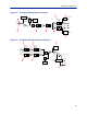
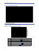
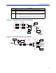
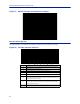
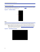
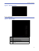
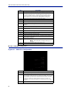
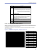
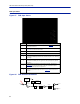
Table Of Contents
- Safety Precautions
- About This Manual
- Table of Contents
- Chapter 1 Introduction
- Chapter 2 System Description
- Chapter 3 Installation guidelines
- Chapter 4 DAS Software Configuration
- Chapter 5 Commissioning
- Chapter 6 RF Commissioning
- Chapter 7 Troubleshooting
- Alarms
- Base Station Gateway (BGW) Alarms
- Fiber Optic Remote (FOR) Alarms
- Remote Unit (RU) Alarms
- Fiber optic Interface (FOI) Alarms
- Base Station Interface (BIU) Alarms
- Medium Power Amplifier (PA) Alarms
- Variable Gain Amplifier (VGA) Alarms
- Analog Pre-distortion (APD) Amplifier Alarms
- Multi-carrier Power Amplifier Interface (MPI) alarms
- Alarms
- Chapter 8 Model Identification

Fiber Distributed Antenna System (Fiber DAS)
81
Figure 83 FOI Opto Status DOI401
FOI Opto and Attenuator Settings
This page will allow changes to be made to the FOI values
Figure 84
1
2
3
4
5
6
7
8
9
10
FOI Opto and Attenuator Settings
Item Description
1 Downlink path 1 attenuator #1. See item 1 in
Figure 85
for measurement location.
2 Downlink path 1 attenuator #2. See item 2 in
Figure 85
for location on the FOI circuitry.
3 Downlink path 2 attenuator #1. See item 3 in
Figure 85
for location on the FOI circuitry.
4 Downlink path 2 attenuator #2. See item 4 in
Figure 85
for location on the FOI circuitry.
5 Uplink common path attenuator #1. See item 5 in
Figure 86
for location on the FOI circuitry.
6 Uplink common path attenuator #2. See item 6 in
Figure 86
for location on the FOI circuitry.
7 Uplink path 1 attenuator. See item 7 in
Figure 86
for location on the FOI circuitry.