
Operation Manual
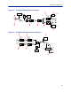
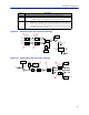
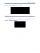
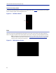
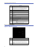
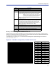
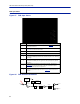
Table Of Contents
- Safety Precautions
- About This Manual
- Table of Contents
- Chapter 1 Introduction
- Chapter 2 System Description
- Chapter 3 Installation guidelines
- Chapter 4 DAS Software Configuration
- Chapter 5 Commissioning
- Chapter 6 RF Commissioning
- Chapter 7 Troubleshooting
- Alarms
- Base Station Gateway (BGW) Alarms
- Fiber Optic Remote (FOR) Alarms
- Remote Unit (RU) Alarms
- Fiber optic Interface (FOI) Alarms
- Base Station Interface (BIU) Alarms
- Medium Power Amplifier (PA) Alarms
- Variable Gain Amplifier (VGA) Alarms
- Analog Pre-distortion (APD) Amplifier Alarms
- Multi-carrier Power Amplifier Interface (MPI) alarms
- Alarms
- Chapter 8 Model Identification

DAS Software Configuration
82
Figure 85 Downlink Opto and Attenuator Settings
DETECTOR
LASER
DRIVER
ETHERNET
MODEM
OPTO OUT
DETECTOR
MONITOR
TX-LVL
DL IN 1
DL IN 2
TP DL
STEP ATT
Attenuator 1
Downlink 1
Attenuator 1
Downlink 2
Attenuator 2
Downlink 1
Attenuator 2
Downlink 2
STEP ATT
STEP ATT
STEP ATT
1
2
3
4
Figure 86 Uplink Opto and Attenuator Settings
DETECTOR
DETECTOR
CURRENT
SENSOR
ETHERNET
MODEM
OPTO IN
RX-LVL
UL OUT 2
UL OUT 1
TP UL
Attenuator
Common 1
PHOTO
DETECTOR
Attenuator
Common 2
Attenuator
Uplink 1
Attenuator
Uplink 2
STEP ATT STEP ATT
STEP ATT
STEP ATT
RX POWER 1
RX POWER 2
6
5
7
8
8 Uplink path 2 attenuator. See item 8 in
Figure 86
for location on the FOI circuitry.
9
RF ON Yes set the UL values as selected above. RF No turns off laser
.
Note: Setting to “No” will disconnect connectivity to the remote(s)
10
Subcarrier TX Power is used for the communications and control signaling of the DAS.
Default setting is -10dBm for single port FOI cards and 0dBm for the 4-port F
OI card.
The value may need to be changed in situations where fiber loss is near the maximum
and communications issues arise. Unnecessarily increasing the subcarrier TX power
may affect RF performance of the DAS.
Item Description