
Operation Manual
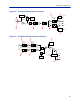
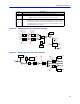
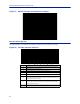
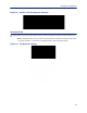
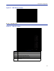
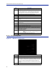
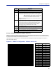
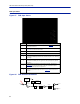
Table Of Contents
- Safety Precautions
- About This Manual
- Table of Contents
- Chapter 1 Introduction
- Chapter 2 System Description
- Chapter 3 Installation guidelines
- Chapter 4 DAS Software Configuration
- Chapter 5 Commissioning
- Chapter 6 RF Commissioning
- Chapter 7 Troubleshooting
- Alarms
- Base Station Gateway (BGW) Alarms
- Fiber Optic Remote (FOR) Alarms
- Remote Unit (RU) Alarms
- Fiber optic Interface (FOI) Alarms
- Base Station Interface (BIU) Alarms
- Medium Power Amplifier (PA) Alarms
- Variable Gain Amplifier (VGA) Alarms
- Analog Pre-distortion (APD) Amplifier Alarms
- Multi-carrier Power Amplifier Interface (MPI) alarms
- Alarms
- Chapter 8 Model Identification

Fiber Distributed Antenna System (Fiber DAS)
83
Figure 87 DOI401 FOI Opto and Attenuator Settings
FOI Fiber Network Subunits
This page provides a visual indication on the fiber link status for each connection to the FOI.
Figure 88
1
2
3
4
5
6 7
8
FOI Fiber Network Subunits
Item Description
1 Selecting the remote link will direct the browser to the Remote Unit page.
2 Network IP address of the FOI card.
3 Optical wavelength of the transmit laser in the FOI card.
4 Subcarrier optical loss between the FOI and FOR in the downlink path.
5 Subcarrier optical loss between the FOR and FOI in the uplink path.
6
Subcarrier power to the modem in the downlink path of the FOR - Range
should be -30 to -60. If the level is too high or too low communication and
other system problems may occur.
7
Subcarrier power to the modem in the uplink path of the FOI - Range should
be -30 to -60. If the level is too high or too low communication and other
system problems may occur.
8 MAC address of the FOI card