
Operation Manual
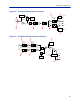
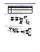
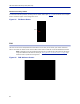
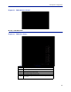
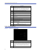
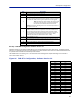
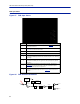
Table Of Contents
- Safety Precautions
- About This Manual
- Table of Contents
- Chapter 1 Introduction
- Chapter 2 System Description
- Chapter 3 Installation guidelines
- Chapter 4 DAS Software Configuration
- Chapter 5 Commissioning
- Chapter 6 RF Commissioning
- Chapter 7 Troubleshooting
- Alarms
- Base Station Gateway (BGW) Alarms
- Fiber Optic Remote (FOR) Alarms
- Remote Unit (RU) Alarms
- Fiber optic Interface (FOI) Alarms
- Base Station Interface (BIU) Alarms
- Medium Power Amplifier (PA) Alarms
- Variable Gain Amplifier (VGA) Alarms
- Analog Pre-distortion (APD) Amplifier Alarms
- Multi-carrier Power Amplifier Interface (MPI) alarms
- Alarms
- Chapter 8 Model Identification

DAS Software Configuration
86
Figure 93 FOR Welcome Screen
RF Strip 1 XXX MHz Status
Figure 94 FOR RF 1 Status
1
2
3
4
5
6
7
8
9
10
11
12
13
17
14
18
16
15
19
Item Description
1 Downlink frequency band for the RF path/strip selected
2 RF link setting for the downlink path: On or Off.
3 Downlink low power alarm turned On or Off.
4 Setting of the downlink ALC threshold.
5 Gain setting for the RF path under review.
6
Maximum allowed gain will always be the same as the set gain except in
special builds.