
Operation Manual
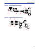
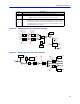
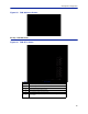
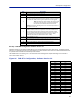
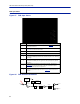
Table Of Contents
- Safety Precautions
- About This Manual
- Table of Contents
- Chapter 1 Introduction
- Chapter 2 System Description
- Chapter 3 Installation guidelines
- Chapter 4 DAS Software Configuration
- Chapter 5 Commissioning
- Chapter 6 RF Commissioning
- Chapter 7 Troubleshooting
- Alarms
- Base Station Gateway (BGW) Alarms
- Fiber Optic Remote (FOR) Alarms
- Remote Unit (RU) Alarms
- Fiber optic Interface (FOI) Alarms
- Base Station Interface (BIU) Alarms
- Medium Power Amplifier (PA) Alarms
- Variable Gain Amplifier (VGA) Alarms
- Analog Pre-distortion (APD) Amplifier Alarms
- Multi-carrier Power Amplifier Interface (MPI) alarms
- Alarms
- Chapter 8 Model Identification

DAS Software Configuration
88
RF Strip 1 XXX MHz Configuration Software Version 3.9
Software release 3.9 introduces settable Return Loss measurements and control over alarms. The default interval
setting is “0” indicating the return loss alarm feature is turned off. Return loss alarms are often disabled when there
is a passive antenna network installed beyond the remote.
The default Return Loss setting is "9". The remote will start shutting down and/or PA damage can result with a
return loss of lower than 6.
Figure 96 FOR RF 1 Configuration, Software Version 3.9
Return Loss (db) VSWR
9.542 2.00
9.262 2.05
8.999 2.10
8.752 2.15
8.519 2.20
8.299 2.25
8.091 2.30
7.894 2.35
7.707 2.40
7.529 2.45
7.360 2.50
7.198 2.55
7.044 2.60
6.896 2.65
6.755 2.70
6.620 2.75
6.490 2.80
6.366 2.85
6.246 2.90
6.131 2.95
6.021 3.00
4 Turns downlink low power alarm on or off.
5 Uplink gain setting for RF path under review.
6
Uplink ALC setting for RF path under review. This is the threshold a
t which
the s
ystem will start reducing further gain to prevent increases in uplink RF
to the FOI. After 10dB decrease in gain an uplink alarm will be triggered
Note: Should be left a factory default. Only change if FOR
uplink gain is changed. If gain is increased on FOR uplink
then the same value should be decreased on the ALC.
Example: Changing the UL FOR gain from 12 to 17 would require ALC to be
changed from -13 to -18.
7
Hardware ALC offset measured in tenths of a dB. Default setting of 60
(6dBm) should be used for most applications. Should the software not be
able to reduce uplink gain fast enough after the ALC threshold has been
exceed, hardware attenuation will be added to protect the uplink path. In
the example above, the hardware attenuation will trigger at -7dBm (-
13dBm ALC threshold minus 6dBm HW ALC offset = -7dBm)
8 Turns uplink RF on or off.
9
Sets uplink test tone frequency. Must be within uplink frequency limits of
the RF module.
10 Turns on uplink test tone. Test tone times out after 60 minutes.
11 Retrieves current FOR settings from system.
Item Description