YOU'RE HEARD, LOUD AND CLEAR. Instruction Manual Vari-Notch® Duplexers (6” Cavities) Manual Part Number 7-9177 8625 Industrial Parkway, Angola, NY 14006 Tel: 716-549-4700 Fax: 716-549-4772 sales@birdrf.com www.bird-technologies.
Warranty This warranty applies for one year from shipping date. TX RX Systems Inc. warrants its products to be free from defect in material and workmanship at the time of shipment. Our obligation under warranty is limited to replacement or repair, at our option, of any such products that shall have been defective at the time of manufacture. TX RX Systems Inc. reserves the right to replace with merchandise of equal performance although not identical in every way to that originally sold. TX RX Systems Inc.
Manual Part Number 7-9177 Copyright © 1997 TX RX Systems, Inc. First Printing: September 1997 Version Number Version Date 1 09/19/97 Symbols Commonly Used WARNING ESD Elecrostatic Discharge CAUTION or ATTENTION Hot Surface High Voltage Electrical Shock Hazard Use Safety Glasses Bird Technologies Group NOTE Important Information TX RX Systems Inc.
GENERAL DESCRIPTION Vari-Notch® duplexers are used to provide simultaneous operation of a transmitter and receiver (or two transmitters) which are operating at different frequencies while connected to a common antenna. These duplexers are frequently used in radio repeater systems. This instruction manual (part# 7-9177-1) covers the installation, tuning, and maintenance of Vari-Notch duplexers constructed from 6.625" diameter cavities.
RG214 or RG142 Double-Shielded Cable (Supplied by customer) Interconnect Cable (1/4 λ or 3/4 λ of this) (channels pass freq.) Antenna Cable (1/2 λ of the other) (channels pass freq.
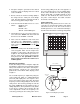
Equipment Port Resonant Cavity Coarse Tuning Lock 10-32 Cap Screw Equipment Port Coarse Tuning Rod Calibration Index Antenna Port Interconnect Cabl e Interconnect Cable Variable Capacitor Access Barrel Mounting Bar Loop Plate Hole Cover Fine Tuning Rod Loop Plate Hold Down Screws Fine Tuning Lock Knurled Thumb Nut Antenna Cable Antenna Cable Loop Plate Assembly Figure 2: Top view of a typical four-cavity Vari-Notch Duplexer (6.625" diameter cavities).
total of 1.5 dB of insertion loss. The total insertion loss is the sum of losses from each cavity in the channel as well as from the interconnecting cables between the cavities. Required Equipment Due to the sensitivity of the adjustments, it is strongly recommended that the proper equipment be used when tuning the individual filters, otherwise the filter should be sent to the factory or an authorized representative for retuning.
2. Set-up the analyzer / generator for the desired frequency (center of display) and for a vertical scale of 10 dB/div. 3. Do not connect the return loss bridge (RLB) to the cavity, leave the "load" port on the bridge open. This will supply the maximum amount of reflected energy to the analyzer input. 4. Insure that the IFR A-7550 menu's are set as follows: DISPLAY - line MODE - live FILTER - none SETUP - 50 ohm/dBm/gen1. decreased by pulling it out; the exact opposite of the coarse tuning rod.
1. Reassemble the duplexer by reinstalling the cavities and interconnect cables in their original locations. 2. The passband for the channels are fine tuned first, in a manner very similar to tuning a single cavity. 3. A zero reference for return loss must be established at the IFR-7550. Connect the RLB to the analyzer / generator as shown in figure 3. 2. Insure that the IFR A-7550 menu's are set as follows: DISPLAY - line MODE - live FILTER - none SETUP - 50 ohm/dBm/gen1.
4. Set-up the analyzer / generator to the desired frequency (center of display) and for a vertical scale of 10 dB/div. with the 50 ohm load. The equipment port of the remaining duplexer channel is left disconnected, refer to figure 6. 5. Do not connect the RLB to the duplexer at this time, leave the "load" port on the bridge open. This will supply the maximum amount of reflected energy to the analyzer input. 10.
14. Terminate the antenna connector with a 50 ohm load. Connect the output of the tracking generator to the equipment port of one of the duplexer channels and the spectrum analyzer input to the equipment port of the remaining channel as shown in figure 7. 15. Set-up the analyzer / generator to sweep across the rejection notch frequency of the channel being tuned. The center of the display should be set to the desired center frequency of the rejection notch being adjusted.
DUPLEXER PROBLEMS AND REMEDIES Duplexers are passive devices requiring little or no service once installed in a system. The proper design and application of a given Duplexer will give years of trouble free service. When problems do occur in a duplex system it is necessary to identify as many abnormal conditions as possible to zero in on the specific cause of the problem.
2. Check the unit label. If needed, the duplexer may be field tuned. Consult the instructions and/or the factory if the duplexer is still under warranty or beyond field tuning capability. 3. Check cable, by substitution, using a termaline wattmeter, or a thruline wattmeter into a known good load. Check the antenna line input for reflected power. 4. To eliminate high input VSWR reduce the number of between series adapters by making up proper interconnect cables.
POWER IN/OUT VS. INSERTION LOSS The graph below offers a convenient means of determining the insertion loss of filters, duplexers, multicouplers and related products. The graph on the back page will allow you to quickly determine VSWR. It should be remembered that the field accuracy of wattmeter readings is subject to considerable variance due to RF connector VSWR and basic wattmeter accuracy, particularly at low end scale readings.
POWER FWD./REV. VS. VSWR 500 400 V S W R 300 200 100 FORWARD POWER (WATTS) 1.1:1 50 40 1.15:1 30 1.2:1 20 1.25:1 1.3:1 10 1.4:1 5.0 4.0 1.5:1 3.0 1.6:1 1.8:1 2.0 2.0:1 1.0 2.5:1 3.0:1 0.5 40 20 10 8.0 6.0 4.0 2.0 1.0 0.8 0.6 0.4 0.2 REFLECTED POWER (WATTS) FOR OTHER POWER LEVELS, MULTIPLY BOTH SCALES BY THE SAME MULTIPLIER TX RX Systems Inc.
Power Ratio and Voltage Ratio to Decibel Conversion Chart Loss or Gain +9.1 dB -9.1 dB Power Ratio 8.128 0.123 Voltage Ratio 2.851 0.351 - dB + Voltage Ratio 1 0.989 0.977 0.966 0.955 0.944 0.933 0.923 0.912 0.902 0.891 0.881 0.871 0.861 0.851 0.841 0.832 0.822 0.813 0.804 0.794 0.785 0.776 0.767 0.759 0.75 0.741 0.733 0.724 0.716 0.708 0.7 0.692 0.684 0.676 0.668 0.661 0.653 0.646 0.638 0.631 0.624 0.617 0.61 0.603 0.596 0.589 0.582 0.575 0.569 Power Ratio 1 0.977 0.955 0.933 0.912 0.891 0.871 0.851 0.
Power Conversion Chart dBm to dBw to Watts to Volts dBm dBw Watts Volts 50Ω dBm dBw Watts Volts 50Ω 80 50 100kW 2236 18 -12 63 mW 1.78 75 45 31.6 kW 1257 17 -13 50 mW 1.58 70 40 10.0 kW 707 16 -14 40 mW 1.41 65 35 3.16 kW 398 15 -15 32 mW 1.26 60 30 1000 224 14 -16 25 mW 1.12 55 25 316 126 13 -17 20 mW 1.00 50 20 100 70.7 12 -18 16 mW 0.890 45 15 31.6 39.8 11 -19 13 mW 0.793 40 10 10.0 22.4 10 -20 10 mW 0.707 38 8 6.31 17.
Return Loss vs. VSWR Watts to dBm Return Loss VSWR Watts dBm 30 1.06 300 54.8 25 1.11 250 54.0 20 1.20 200 53.0 19 1.25 150 51.8 18 1.28 100 50.0 17 1.33 75 48.8 16 1.37 50 47.0 15 1.43 25 44.0 14 1.50 20 43.0 13 1.57 15 41.8 12 1.67 10 40.0 11 1.78 5 37.0 10 1.92 4 36.0 9 2.10 3 34.8 2 33.0 1 30.
8625 Industrial Parkway, Angola, NY 14006 Tel: 716-549-4700 Fax: 716-549-4772 sales@birdrf.com www.bird-technologies.