
Manual


15
Remote Computer Connector
To communicate with a BPM-E that is connected to the RS-232 port at the rear
of the 3129 Digital Display, connect a PC to the Remote Computer connector on
the front panel of the display. When connected in this manner, signals are
routed directly from the BPM-E through the display to the PC.
To setup a BPM-E connected to the Remote Computer connector (as described
above), follow the setup instructions for RS-232 and PC Tool software in "Setting
Up the BPM-E" on page 19.
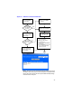
Power/Alarm Connector
The Power/Alarm connector provides operating power to the BPM-E and receives
signals and data from the BPM-E. Pin numbers and descriptions are given in
Figure 7, page 16 and a typical connection is illustrated in Figure 8 on page 17.
Power ON/OFF Switch
The power switch on the front of the display turns the unit ON or OFF.
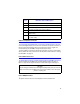
Pin #
(Fig. 6)
New Label Text and Description
1 Ground
2 Remote Reset (reset TTL alarm signal, TTL low = reset)
3 Alrm TTL Out (low = alarm)
4 Common for Alrm (relay contact common)
5 Open No Alrm (relay energized, contacts are open when no
alarm exists)
6 Closed No Alrm (relay energized, contacts are closed when
no alarm exists)
CAUTION
The DC voltage provided by the 3129 Digital Display power/alarm port should
only be used to power the BPM-E. Do not use the 3129 DC source to supply
power to anything else.