INSTRUCTION BOOK Terminating Power Sensors & Extended Frequency Terminating Power Sensors Models 5011, 5011-EF, 5015 and 5015-EF ©Copyright 2009 by Bird Electronic Corporation Instruction Book Part Number 920-5011S Rev.
Safety Precautions The following are general safety precautions that are not necessarily related to any specific part or procedure, and do not necessarily appear elsewhere in this publication. These precautions must be thoroughly understood and apply to all phases of operation and maintenance. WARNING Keep Away From Live Circuits Operating Personnel must at all times observe general safety precautions.
WARNING Safety Earth Ground An uniterruptible earth safety ground must be supplied from the main power source to test instruments. Grounding one conductor of a two conductor power cable is not sufficient protection. Serious injury or death can occur if this grounding is not properly supplied. WARNING Resuscitation Personnel working with or near high voltages should be familiar with modern methods of resuscitation.
Warning Statements The following safety warnings appear in the text where there is danger to operating and maintenance personnel, and are repeated here for emphasis. Caution Statements The following equipment cautions appear in the text and are repeated here for emphasis. CAUTION Do not exceed 2 W average or 125 W peak power for 5 µs when using the TPS or the TPS-EF. Doing so will render the sensor inoperative. On page 1 and 3. CAUTION Discharge all static potentials before connecting the TPS(-EF).
Safety Statements USAGE ANY USE OF THIS INSTRUMENT IN A MANNER NOT SPECIFIED BY THE MANUFACTURER MAY IMPAIR THE INSTRUMENT’S SAFETY PROTECTION. USO EL USO DE ESTE INSTRUMENTO DE MANERA NO ESPECIFICADA POR EL FABRICANTE, PUEDE ANULAR LA PROTECCIÓN DE SEGURIDAD DEL INSTRUMENTO. BENUTZUNG WIRD DAS GERÄT AUF ANDERE WEISE VERWENDET ALS VOM HERSTELLER BESCHRIEBEN, KANN DIE GERÄTESICHERHEIT BEEINTRÄCHTIGT WERDEN.
SERVICE SERVICING INSTRUCTIONS ARE FOR USE BY SERVICE - TRAINED PERSONNEL ONLY. TO AVOID DANGEROUS ELECTRIC SHOCK, DO NOT PERFORM ANY SERVICING UNLESS QUALIFIED TO DO SO. SERVICIO LAS INSTRUCCIONES DE SERVICIO SON PARA USO EXCLUSIVO DEL PERSONAL DE SERVICIO CAPACITADO. PARA EVITAR EL PELIGRO DE DESCARGAS ELÉCTRICAS, NO REALICE NINGÚN SERVICIO A MENOS QUE ESTÉ CAPACITADO PARA HACERIO. WARTUNG ANWEISUNGEN FÜR DIE WARTUNG DES GERÄTES GELTEN NUR FÜR GESCHULTES FACHPERSONAL.
ASSISTENZA TECNICA LE ISTRUZIONI RELATIVE ALL’ASSISTENZA SONO PREVISTE ESCLUSIVAMENTE PER IL PERSONALE OPPORTUNAMENTE ADDESTRATO. PER EVITARE PERICOLOSE SCOSSE ELETTRICHE NON EFFETTUARRE ALCUNA RIPARAZIONE A MENO CHE QUALIFICATI A FARLA.
RF VOLTAGE MAY BE PRESENT IN RF ELEMENT SOCKET - KEEP ELEMENT IN SOCKET DURING OPERATION. DE LA TENSION H.F. PEAT ÊTRE PRÉSENTE DANS LA PRISE DE L'ÉLÉMENT H.F. - CONSERVER L'ÉLÉMENT DANS LA PRISE LORS DE L'EMPLOI. HF-SPANNUNG KANN IN DER HF-ELEMENTBUCHSE ANSTEHEN - ELEMENT WÄHREND DES BETRIEBS EINGESTÖPSELT LASSEN. PUEDE HABER VOLTAJE RF EN EL ENCHUFE DEL ELEMENTO RF - MANTENGA EL ELEMENTO EN EL ENCHUFE DURANTE LA OPERACION.
About This Manual This manual covers the operating and maintenance instructions for the following models: 5011 5011-EF 5015 5015-EF Changes to this Manual We have made every effort to ensure this manual is accurate. If you discover any errors, or if you have suggestions for improving this manual, please send your comments to our Solon, Ohio factory. This manual may be periodically updated. When inquiring about updates to this manual refer to the part number and revision on the title page.
viii
Table of Contents Safety Precautions 0 Safety Symbols. . . . . . . . . . . . . . . . . . . . . . . . . . . . . i Warning Statements . . . . . . . . . . . . . . . . . . . . . . . ii Caution Statements . . . . . . . . . . . . . . . . . . . . . . . . ii Safety Statements . . . . . . . . . . . . . . . . . . . . . . . . . iii About This Manual vii Changes to this Manual . . . . . . . . . . . . . . . . . . . vii Literature Contents . . . . . . . . . . . . . . . . . . . . . . . vii Chapter Layout . . . . . . . . .
x
Chapter 1 Introduction Description The Bird 5015 Terminating Power Sensor (TPS) is a diode-based power sensor that measures true average power from 40 MHz to 4 GHz and from –20 dBm to +10 dBm. For best results, wait 5 minutes after applying power to the sensor before taking readings. CAUTION Do not exceed 2 W average or 125 W peak power for 5 µs when using the TPS or the TPS-EF. Doing so will render the sensor inoperative.
2
Chapter 2 Installation Connecting Terminating Power Sensor (TPS) CAUTION Discharge all static potentials before connecting the TPS(-EF). Electrostatic shock could damage the sensor. CAUTION When connecting the TPS or the TPS-EF, only turn the connector nut. Damage may occur if torque is applied to the sensor body. CAUTION Do not exceed 2 W average or 125 W peak power for 5 µs when using the TPS or the TPS-EF. Doing so will render the sensor inoperative.
1. Do one of the following: z To connect to a Digital Power Meter: z For Models 5011 and 5011EF: Connect the Bird TPS to the “Sensor” serial port on the DPM using the sensor cable provided. z For Models 5015 and 5015-EF: Connect the Bird TPS to the “Sensor” USB port on the DPM using the sensor cable provided. Note: An attenuator or directional coupler should be used with the TPS in most applications. Note: For an RF source with output between 0.1 and 50 W, use a 40 dB, 50 W attenuator.
Chapter 3 Operation Zeroing Sensor Over time, the sensor’s “zero value” (reading with no applied RF power) can drift, making all readings inaccurate by this value. For example, if the zero value is – 0.02 W, measuring a 50 W signal will give a reading of 49.98 W, a 0.04% error. Measuring a 1 W signal will give a reading of 0.98 W, a 2% error. If the drift would be a significant error, rezero the sensor: 1. Ensure the sensor has reached a stable operating temperature. 2.
Example - If a sensor has a specified accuracy of 5% of reading + 1.0 uW, then for a 10 mW signal the uncertainty is ± 0.501 mW. For a 1 mW signal the measurement uncertainty is ± 0.051 mW. Sensor Uncertainty While this value is a good estimate, the sensor is actually more accurate. The sensor’s accuracy also depends on the temperature, and the power and frequency of the source; Table 1 lists some examples of uncertainty factors.
Othera Resolution Zero Set† Noiseb < 40 °C or > 100 MHz ± 0.50% ± ½ smallest displayed digit (e.g. for a mW scale, three decimal places are displayed. ½ the smallest is 0.5 µW) ± 0.125 µW above 1.05 mW ± 0.7 µW 105 µW to 1.05 mW ± 0.4 µW below 105 µW ± 0.2 µW a. Above 40 °C, when making measurements at frequencies between 40 and 100 MHz, add 1.1%. b.
Table 3 has two examples of uncertainty calculations. The first is a 10 mW signal at room temperature. The second is a 10 µW, 40 MHz signal at 50°C. Since this measurement is at both low frequency and high temperature, the uncertainty will be increased. Note that the RSS uncertainties are smaller than the values from the rough estimate. This will always be the case. Table 3 - Uncertainty Examples Example 1 (10 mW, Room Temp) 8 Error Source Percent Uncert. RSS Term Cal. Uncert. Freq. Resp. Temp. Lin.
Mismatch Uncertainty Another factor of measurement accuracy is mismatch uncertainty. When a source and a load have different impedances, some signal will be reflected back to the source. This uncertainty depends on both the VSWR of the TPS and the VSWR of the rest of the system. For a system VSWR of 1.0, the mismatch uncertainty would be 0. For a VSWR of 5.0, the mismatch uncertainty would be 12.5%. Given the VSWR of the TPS and the source, the mismatch uncertainty can be calculated as follows.
Note: If a source with a 1.30:1 VSWR was used instead, the mismatch uncertainty would be: ρ s = ( 1.30 – 1 ) ⁄ ( 1.30 + 1 ) = 0.130 ρ 1 = ( 1.20 – 1 ) ⁄ ( 1.20 + 1 ) = 0.091 2 MU = [ ( 1 + 0.130 × 0.091 ) – 1 ] × 100 = ± 2.39 Using a lower VSWR source can drastically reduce the mismatch uncertainty. Keep in mind that the typical VSWR of the Model 5011 is 1.03:1, which gives a much lower mismatch uncertainty. Example - With the 1.50:1 source, the mismatch uncertainty would be: ρ s = ( 1.50 – 1 ) ⁄ ( 1.
Chapter 4 Specifications 5011 Specifications Power Measurement Characteristics General Terminated average power Frequency Range 40 MHz to 4 GHz Power Measurement Range –20.0 to +10.0 dBm (10 µW to 10 mW) Maximum Power 2 W avg., 125 W peak for 5 µs Peak/Average Ratio 12 dB maximum Accuracy ± (5% of readinga + 1.0 µW) (excluding mismatch uncertainty) No correction factors necessary Input Impedance 50 Ohms (nominal) Input VSWR: Typical Maximum 1.03 (36.6 dB return loss) 1.20 (20.
Physical and Environmental Specifications Operating Temp. –10 to +50 °C (+14 to +122 °F) Storage Temp. –40 to +80 °C (–40 to +176 °F) Mechanical Shock IAW MIL-PRF-28800F class 3 Vibration IAW MIL-PRF-28800F class 3 Humidity 95% maximum (non-condensing) Altitude 15,000 ft. operating Dimensions 6” long max (including connectors); 1.5” diameter nominal Weight 3/4 lb. max.
Input Impedance 50 Ohms (nominal) Input VSWR: Typical Maximum 1.05 (32.0 dB return loss) 1.25 (19.1 dB return loss) Input Connector Precision N Male Output Connector Male DB-9 to host instrument Power Supply From host instrument via cable connection a. Above 40 °C or below 10 °C add 1%. Physical and Environmental Specifications Operating Temp. –10 to +50 °C (+14 to +122 °F) Storage Temp.
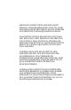
MALE DB-9 CONNECTOR PRECISION "N" MALE CONNECTOR 4 1/4" [108 mm] ® Series 5011™ Terminating Power Sensor 6” [152 mm] 14 Bird Electronic Corp., Solon, Ohio USA Web: http://www.bird-electronic.
5015 Specifications Power Measurement Characteristics General Terminated average power Frequency Range 40 MHz to 4 GHz Power Measurement Range –20.0 to +10.0 dBm (10 µW to 10 mW) Maximum Power 2 W avg., 125 W peak for 5 µs Peak/Average Ratio 12 dB maximum Accuracy ± (5% of readinga + 1.0 µW) (excluding mismatch uncertainty) No correction factors necessary Input Impedance 50 Ohms (nominal) Input VSWR: Typical Maximum 1.03 (36.6 dB return loss) 1.20 (20.
Physical and Environmental Specifications Operating Temp. –10 to +50 °C (+14 to +122 °F) Storage Temp. –40 to +80 °C (–40 to +176 °F) Mechanical Shock IAW MIL-PRF-28800F class 3 Vibration IAW MIL-PRF-28800F class 3 Humidity 95% maximum (non-condensing) Altitude 15,000 ft. operating Dimensions 6” long max (including connectors); 1.5” diameter nominal Weight 3/4 lb. max.
Input VSWR: Typical Maximum 1.05 (32.0 dB return loss) 1.25 (19.1 dB return loss) Input Connector Precision N Male Output Connector SeaLatch USB type to host instrument Power Supply From host instrument via cable connection a. Above 40 °C or below 10 °C add 1%. Physical and Environmental Specifications Operating Temp. –10 to +50 °C (+14 to +122 °F) Storage Temp.
18
Limited Warranty All products manufactured by Seller are warranted to be free from defects in material and workmanship for a period of one (1) year, unless otherwise specified, from date of shipment and to conform to applicable specifications, drawings, blueprints and/or samples.