YOU'RE HEARD, LOUD AND CLEAR. Installation Instructions for SBII 800 MHz Filter Conversion Kit Part# 89-89A-05041-3/5/10/15/18/10-18/15-18 Manual Part Number 7-9424 8625 Industrial Parkway, Angola, NY 14006 Tel: 716-549-4700 Fax: 716-549-4772 sales@birdrf.com www.bird-technologies.
Warranty This warranty applies for one year from shipping date. TX RX Systems Inc. warrants its products to be free from defect in material and workmanship at the time of shipment. Our obligation under warranty is limited to replacement or repair, at our option, of any such products that shall have been defective at the time of manufacture. TX RX Systems Inc. reserves the right to replace with merchandise of equal performance although not identical in every way to that originally sold. TX RX Systems Inc.
Manual Part Number 7-9424 Copyright © 2006 TX RX Systems, Inc. First Printing: July 2006 Version Number Version Date 1 07/24/06 Symbols Commonly Used WARNING ESD Elecrostatic Discharge CAUTION or ATTENTION Hot Surface High Voltage Electrical Shock Hazard Use Safety Glasses Bird Technologies Group NOTE Important Information TX RX Systems Inc.
Table of Contents Section 1 General Description ........................................................................................... 1 Types of 800 MHz SBII Re-banding kits.............................................................. 1 Procedure for Non-18 MHz Systems ................................................................... 1 Procedure for 18 MHz Systems...........................................................................
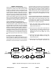
GENERAL DESCRIPTION These instructions are for rebanding 800 Mhz Signal Booster II systems in the field. Caution should be taken not to drop the filters or sharply bump the tuning rods located on the top of the filters, doing so could result in de-tuning of the filters. The conversion process consists of replacing the original filters with new ones, adding a signal sampler if required, replacing the Tee-connector as well as several critical length cables.
cables at the filter. Two of cables run to a teeconnector and one of the cables runs to the card cage. 7) Install the replacement filters in reverse order making sure that the mounting plates are firmly attached to the cabinet. Rebanding 3 MHz systems. SB II systems with an original 3 MHz bandwidth use an extra filter in series with the preselector on the left side of the cabinet. This extra filter is mounted horizontally at the top of the cabinet.
Procedure for 18 MHz Systems Re-banding kits for systems that originally left the factory as 18 MHz systems will consist of replacement filters which have the new desired bandwidth, new tee-connectors, several critical length cables, as well as a signal sampler. The filters are pretuned at the factory so the position of the tuning rods should not be changed.
TXRX Systems Inc.
TXRX Systems Inc.
TXRX Systems Inc.
TXRX Systems Inc.
TXRX Systems Inc.
TXRX Systems Inc.
TXRX Systems Inc.
TXRX Systems Inc.
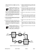
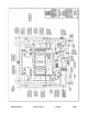
07/24/06 LOCKWASHER PART No. 8-6791 2 - PLACES GROUNDING STRAP No. 8-20120 TO BE ATTACHED TO GROUND STUD ON ENCLOSURE & DOOR USING HARDWARE SUPPLIED WITH ENCLOSURE *SEE DETAIL 'B' ON PAGE 2 POWER SUPPLY MODULE PART No. 8-20667, MTD. TO MT. BRACKET No. 1-20673 WITH (3) M4 x 8mm P.H.M.S. No. 8-18530 & THEN MTD. TO PANEL WITH (2) 6 - 32 x 3/8" P.H.M.S. No. 8-18492 & (2) #6 SPLIT WASHERS No. 8-6750 4-WAY BACKED MT. PART No. 8-6322 WITH WIRE TIE PART No. 8-6112 PRESELECTOR No. 3-12975, MTD. TO MT.
TXRX Systems Inc.
TXRX Systems Inc.
TXRX Systems Inc.
TXRX Systems Inc.
TXRX Systems Inc.
TXRX Systems Inc.
TXRX Systems Inc.
Power Ratio and Voltage Ratio to Decibel Conversion Chart Loss or Gain +9.1 dB -9.1 dB Power Ratio 8.128 0.123 Voltage Ratio 2.851 0.351 - dB + Voltage Ratio 1 0.989 0.977 0.966 0.955 0.944 0.933 0.923 0.912 0.902 0.891 0.881 0.871 0.861 0.851 0.841 0.832 0.822 0.813 0.804 0.794 0.785 0.776 0.767 0.759 0.75 0.741 0.733 0.724 0.716 0.708 0.7 0.692 0.684 0.676 0.668 0.661 0.653 0.646 0.638 0.631 0.624 0.617 0.61 0.603 0.596 0.589 0.582 0.575 0.569 Power Ratio 1 0.977 0.955 0.933 0.912 0.891 0.871 0.851 0.
Return Loss vs. VSWR Watts to dBm Return Loss VSWR Watts dBm 30 1.06 300 54.8 25 1.11 250 54.0 20 1.20 200 53.0 19 1.25 150 51.8 18 1.28 100 50.0 17 1.33 75 48.8 16 1.37 50 47.0 15 1.43 25 44.0 14 1.50 20 43.0 13 1.57 15 41.8 12 1.67 10 40.0 11 1.78 5 37.0 10 1.92 4 36.0 9 2.10 3 34.8 2 33.0 1 30.
8625 Industrial Parkway, Angola, NY 14006 Tel: 716-549-4700 Fax: 716-549-4772 sales@birdrf.com www.bird-technologies.