Part No. YOU'RE HEARD, LOUD AND CLEAR. 7-9362-2 Installation and Operation Manual for the Two-Way Signal Booster System Model Number 61-89A-50-XXX-XX Copyright © 2005 TX RX Systems Inc. First Printing: March 2004 8625 Industrial Parkway, Angola, NY 14006 Version Number Version Date 1 03/30/04 1.2 04/15/04 2 10/19/05 Tel: 716-549-4700 Fax: 716-549-4772 sales@birdrf.com www.bird-technologies.
Warranty Symbols This warranty applies for one year from shipping date. Commonly Used TX RX Systems Inc. warrants its products to be free from defect in material and workmanship at the time of shipment. Our obligation under warranty is limited to replacement or repair, at our option, of any such products that shall have been defective at the time of manufacture. TX RX Systems Inc.
For Class A Unintentional Radiators This equipment has been tested and found to comply with the limits for a Class A digital device, pursuant to part 15 of the FCC rules. These limits are designed to provide reasonable protection against harmful interference when the equipment is operated in a commercial environment.
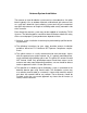
Antenna System Installation The antenna or signal distribution system consists of two branches. An uplink branch typically uses an outdoor mounted, unidirectional gain antenna such as a yagi and a downlink signal radiating system consisting of a network of zero-gain whip antennas or lengths of radiating cable usually mounted inside of the structure. Even though the antenna system may not be supplied or installed by TX RX Systems.
Table of Contents General Description .............................................................................................. 1 Unpacking ....................................................................................................... 1 Installation ....................................................................................................... 1 Location ....................................................................................................... 1 Mounting ..................
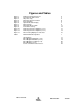
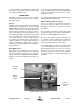
Figures and Tables Figure 1 Figure 2 Figure 3 Figure 4 Figure 5 Figure 6 Figure 7 Figure 8 Figure 9 Figure 10 Figure 11 Figure 12 Figure 13 Cabinet mounting hole layout Front internal cabinet view AC power entry Measuring antenna isolation Boot-up display Operational status display Menu System Measuring Booster Gain Performance Survey Removing the Power Amplifier (1 of 3) Removing the Power Amplifier (2 of 3) Removing the Power Amplifier (3 of 3) Disconnecting Display/User Interface 2 3 4 6 6 7 8 11 12 13
GENERAL DESCRIPTION Signal boosters extend radio coverage into areas where abrupt propagation losses prevent reliable communication. No frequency translation (conversion) occurs with this device. Signal Booster II (SB II) is a broadband, bi-directional signal booster available in a variety of configurations as shown in Table 1. The product model number is used to describe each configuration available. This manual details the installation and operation of the 61-89A50-XXX-XX series of boosters.
the unit and the possibility for injury if the unit should become detached from its mounting surfaces for any reason. Although signal boosters can operate for years without being attended to, the unit will need to be accessed by service personnel with troubleshooting equipment, such as digital multimeters and spectrum analyzer or a laptop computer from time to time. The location of the power source will also have a bearing on the mounting location.
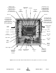
Uplink L/L Card (for Full Gain Model) Attenuator Card (for Mid Gain Model) Attenuator Card (for Low Gain Model) Comm-Card (Optional) Controller Downlink Power Distribution Uplink Power Distribution Downlink L/L Card (for Full Gain Model) Attenuator Card (for Mid Gain Model) Attenuator Card (for Low Gain Model) Test Port Test Port Downlink M/L Card (for Full Gain Model) Downlink M/L Card (for Mid Gain Model) Downlink Low Gain Card (for Low Gain System) Uplink M/L Card (for Full Gain Model) Uplink M/L
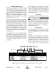
It is the customer’s responsibility to make sure these devices are mounted safely and in compliance with local building codes. CONNECTIONS All cabling connections to the booster should be made and checked for correctness prior to powering up the system. AC Line Signal Booster II is designed to be hard-wired to 110 single phase AC lines at 50 - 60 Hz (see Figures 2 and 3). An AC line filter is provided for this purpose. There is a hole provided in the cabinet bottom-wall for bringing in the AC line.
Use of these terminals is optional. SB II also has a number of status LEDs built-in to individual modules to indicate a fault condition. RF Connections N(F) bulkhead connectors are provided on the bottom of the cabinet for connection to the signal distribution system. Be sure that the correct branch of the distribution system is connected to its corresponding Uplink/Downlink connector or the system will not work properly. Using high-quality connectors with gold center pins is advised.
EXTERNAL ANTENNA INTERNAL SIGNAL DISTRIBUTION SYSTEM SPECTRUM ANALYZER SIGNAL GENERATOR ISOLATION (dB) ZERO LOSS REFERENCE Figure 4: Typical test equipment interconnection for measuring antenna isolation. It is wise to repeat the procedure listed above for measuring antenna isolation with the signal generator set to frequencies at the passbands edges in order to see if the isolation is remaining relatively constant over the complete width of the passband.
2) The two green OLC light bars will be fully lit along their length for approximately 5 seconds. 12V: Green indicates the 12 volt DC power system is operating properly. 3) The LCD display shows the firmware revision screen for about 5 seconds (see Figure 5). UL PA: Green indicates that the uplink power amplifier is drawing current within the expected operating range and at a safe temperature.
NOTE: If no button is pressed within 2 minutes, system returns to Main Status Display Screen UL: DL: GAIN ## dB ## dB 61-89A-50 USER MENU 1 (8-20460A) OUT LVL ## dBm ## dBm KEY E Press ENTER key SBII Status OK Press Item Select arrow key E Detailed Status Calibrate Currents Uplink Low Level Amp Set Gain Uplink Mid Level Amp E Set Output Level E E E E Configuration E E NOTE: Pressing CANCEL always returns you to the previous menu without saving changes E E Uplink Power Amp E Change G
will return to this display from any other display if none of the menu interface buttons are pressed within 2 minutes. The exception is the OLC status display which does require a button press to exit. The main status display shows the uplink and downlink gain in dB as well as the uplink and downlink output level in dBm. The last line of the main status display gives a summary status message for the entire signal booster. In this example “Status OK” is being displayed.
Done using the arrow keys and press enter to return to the menu. Use the Cancel button to return to the Status Display. briefly lit. Constant light bar activity means the booster gain needs to be reduced for optimum performance. Detailed Status Screens These items allow a detailed examination of system components including; all amplifiers (current draw and temperature), the power supply (voltage level), and the OLC function (present status and historical archive). Each item is discussed below in detail.
individual plug-in module. These are tri-color LED’s with green representing NORMAL operation, orange representing a WARNING condition, and red indicating a FAULT. A war ning condition occurs when the current draw of the amplifier exceeds nominal by +/- 20%. Fault conditions occur when the current draw exceeds +/- 30% or the amplifiers operating temperature exceeds 80° Celsius. The LED for the attenuator card is green only and indicates DC power applied to the card.
Spectrum Analyzer Signal Distribution System To Donor Signal 10 dB Pad Sample Sample Test Port Test Port Figure 9: Methodology for doing a performance survey of the signal distribution system. lowing is an outline of how to do such a survey. Because the nature of each installation can be quite different, only a broad outline is given. 1) Measure the gain of the signal booster being careful not to exceed the maximum input level. The recommended maximum RF Input power for the SBII is -15 dBm.
Remove Screws Remove Screws Remove Screws Remove Screws Figure 10: Remove 14 mounting screws to detach amplifier assembly from cabinet. 2) Inspect the unit to see that the two power supply LED DC indicators are lit (remove any dust or debris that may obscure the LEDs). This will verify that DC power is flowing properly. Check all hardware for tightness. 3) Compare system performance to initial performance levels measured when the system was first installed.
squeeze the top and bottom of the connector together to release a hold down tab. When properly squeezed the grey cable will disconnect easily from the amplifier. Refer to Figure 12. 4) To replace the amplifier assembly repeat steps 1 through 3 in reverse order. When replacing the RF cables do not overtighten the SMA connectors. They should be tightened just slightly more than hand tight or to the specification of 7 in/lbs.
the SMA connectors. They should be tightened just slightly more than hand tight or to the specification of 7 in/lbs. Modules can be swapped between the uplink and downlink branches for troubleshooting purposes. If a problem exists in one branch and the problem moves to the other branch when modules are swapped around this indicates a defective module. Note: After an amplifier module is replaced use the Calibrate Currents software function to properly set the amplifiers alarm trip point, see page 9.
4) Remove the ribbon cable that connects the display/user interface assembly to the card cage, see Figure 13. 5) To replace the display/user interface assembly repeat steps 1 through 4 in reverse order. Power Supply Replacement The SB II power supply assembly is field replaceable. Follow the steps listed below in sequential order. The required tools are a #1 Phillips screwdriver. Card Cage Replacement To replace the card cage follow the steps listed below in sequential order.
TX RX Systems Inc. 10/19/05 Manual 7-9362-2 Page 17 24" x 24" x 8" < 85 lbs. Net Weight: < 85 lbs. 24" x 24" x 8" NEMA 4, NEMA 4X Rack Mount NEMA 4, NEMA 4X Rack Mount Nominal Size: Housing: <100 VA +24 to +27 VDC 100-240 VAC; 50-60 Hz BNC female N female 50 ohms, <1.5:1 VSWR -30°C to +50° C 6.
TX RX Systems Inc.
TX RX Systems Inc.
TX RX Systems Inc.
TX RX Systems Inc. 10/19/05 24/27 VDC Battery Backup On-Off Switch OLC PS +24 VDC Converter OLC/Temp Manual 7-9362-2 Backplane 3-19832 Controller Card DL2 Bypass UL2 +5 3-19940 Converter +12 +12 +5 V 24v 12v Enter Cancel UL PA DL PA 3-19833 DL Power Distribution Card 3-19833 UL Power Distribution Card 3-19833 3-19833 3-19831 SYSTEMS INC.
CELSIUS TO FAHRENHEIT CONVERSION TABLE CELCIUS FARENHEIT CELCIUS FARENHEIT CELCIUS FARENHEIT CELCIUS FARENHEIT 105 221.0 66 150.8 27 80.6 -12 10.4 104 219.2 65 149.0 26 78.8 -13 8.6 103 217.4 64 147.2 25 77.0 -14 6.8 102 215.6 63 145.4 24 75.2 -15 5.0 101 213.8 62 143.6 23 73.4 -16 3.2 100 212.0 61 141.8 22 71.6 -17 1.4 99 210.2 60 140.0 21 69.8 -18 -0.4 98 208.4 59 138.2 20 68.0 -19 -2.2 97 206.6 58 136.4 19 66.2 -20 -4.
POWER FWD./REV. VS VSWR 500 400 V S W R 300 200 100 1.1:1 FORWARD POWER (Watts) 50 40 1.15:1 30 1.2:1 20 1.25:1 1.3:1 10 1.4:1 5.0 4.0 1.5:1 3.0 1.6:1 1.8:1 2.0 2.0:1 1.0 2.5:1 3.0:1 0.5 40 20 10 8.0 6.0 4.0 2.0 1.0 0.8 0.6 0.4 0.2 REFLECTED POWER (Watts) FOR OTHER POWER LEVELS MULTIPLY BOTH SCALES BY THE SAME MULTIPLIER Bird Technologies Group TX RX Systems Inc.
POWER IN/OUT VS INSERTION LOSS The graph below offers a convenient means of determining the insertion loss of filters, duplexers, multicouplers and related products. The graph on the back page will allow you to quickly determine VSWR. It should be remembered that the field accuracy of wattmeter readings is subject to considerable variance due to RF connector VSWR and basic wattmeter accuracy, particularly at low end scale readings.
Return Loss vs. VSWR Watts to dBm Return Loss VSWR Watts dBm 30 1.06 300 54.8 25 1.11 250 54.0 20 1.20 200 53.0 19 1.25 150 51.8 18 1.28 100 50.0 17 1.33 75 48.8 16 1.37 50 47.0 15 1.43 25 44.0 14 1.50 20 43.0 13 1.57 15 41.8 12 1.67 10 40.0 11 1.78 5 37.0 10 1.92 4 36.0 9 2.10 3 34.8 2 33.0 1 30.
8625 Industrial Parkway, Angola, NY 14006 Tel: 716-549-4700 Fax: 716-549-4772 sales@birdrf.com www.bird-technologies.