
Installation Instructions Instruction Manual


Manual 7-9362-2 Page 12TX RX Systems Inc. 10/19/05
lowing is an outline of how to do such a survey.
Because the nature of each installation can be
quite different, only a broad outline is given.
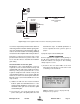
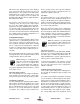
1) Measure the gain of the signal booster being
careful not to exceed the maximum input level.
The recommended maximum RF Input power
for the SBII is -15 dBm. Stronger input signals
will cause the unit to exceed its maximum IM
specifications. Input signals which are stronger
than 0 dBm will physically damage the unit. Fig-
ure 8 shows this being done using a signal gen-
erator and spectrum analyzer. Record the
measured values for each passband. We rec-
ommend that a 50 ohm load be connected to
the unused RF port on the bottom of the cabinet
during the gain test.
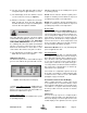
2) The spectrum analyzer is connected to the -30
dB signal sampler port following the final output
amp. This port will allow the observation of the
amplifier output at a considerably reduced out-
put level. This decoupling value (-30 dB) needs
to be added to any measured signal value in
order to arrive at the actual signal level.
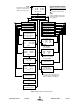
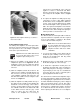
3) With a spectrum analyzer connected to the sig-
nal sampler port (see Figure 9), have person-
nel with handheld radios move to several
predetermined points and key their radios.
Record the level of these signals as observed
on the analyzer and also record the location of
the person transmitting. In this way, a map of
the systems performance can be generated.
4) For signals coming from a fixed antenna or sta-
tion, record the level of all the desired incoming
signals for future reference.
MAINTENANCE AND REPAIR
Signal boosters manufactured by TX RX Systems,
Inc. can perform for years with little maintenance
and repair. However, if the amplifiers are subjected
to excessively high signal levels, power surges or
lightning strikes, failures may occur. The following
procedures may be followed for detecting a mal-
functioning unit or as part of a periodic mainte-
nance program.
1) The heatsink area should be cleared of dust
and debris.
To Donor
Signal
Signal Distribution System
Spectrum
Analyzer
10 dB Pad
S
ampl
e
S
ampl
e
Test Port
Test Port
Figure 9: Methodology for doing a performance survey of the signal distribution system.