
Installation Instructions Instruction Manual


Manual 7-9362-2 Page 13TX RX Systems Inc. 10/19/05
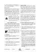
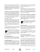
2) Inspect the unit to see that the two power sup-
ply LED DC indicators are lit (remove any dust
or debris that may obscure the LEDs). This will
verify that DC power is flowing properly. Check
all hardware for tightness.
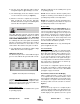
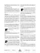
3) Compare system performance to initial perfor-
mance levels measured when the system was
first installed. The lack of signal can be traced
to a malfunctioning amplifier by progressive sig-
nal monitoring from the output (far end) to the
input end of the system noting the area where
the signal returns to normal level. The next
amplifier toward the output end of the system
will probably be the one that failed.
or
Measure the gain at any convenient frequency
in the working frequency band to verify that the
performance is still within specifications.
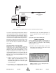
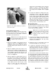
Figure 10: Remove 14 mounting screws to detach amplifier assembly from cabinet.
Remove Screws
Remove Screws
Remove
Screws
Remove
Screws
Figure 11: Slide amplifier towards bottom of cabi-
net to remove upper cable.