
Installation Instructions Instruction Manual


Manual 7-9362-2 Page 14TX RX Systems Inc. 10/19/05
Power Amplifier Replacement
The SB II power amplifiers are field replaceable.
Follow the steps listed below in sequential order.
The required tools are a #1 Phillips screwdriver
and a 5/16” open-ended wrench.
Note: Power to the SB II cabinet must
be turned OFF during the power
amplifier replacement process.
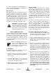
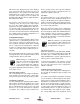
1) Remove the Phillips screws which hold the
amplifier into place, refer to Figure 10. The nuts
holding the screws are pressed into the cabinet
and will remain in place when the screws are
removed.
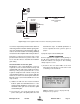
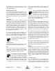
2) Slide the amplifier towards the bottom of the
cabinet as far as it will go. This will allow the top
RF connector to clear the opening. Tilt the top
of the amplifier outwards and remove the top
RF cable at the SMA connector using the 5/16”
wrench. See Figure 11.
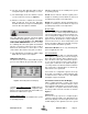
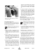
3) Slide the amplifier assembly towards the top of
the cabinet as far as it will go. This will allow the
bottom RF connector and grey control cable to
clear the opening. Tilt the bottom of the ampli-
fier outwards and remove the bottom RF cable
at the SMA connector and the grey control
cable. To remove the grey cable from the
socket on the amplifier it is necessary to
squeeze the top and bottom of the connector
together to release a hold down tab. When
properly squeezed the grey cable will discon-
nect easily from the amplifier. Refer to Figure
12.
4) To replace the amplifier assembly repeat steps
1 through 3 in reverse order. When replacing
the RF cables do not overtighten the SMA con-
nectors. They should be tightened just slightly
more than hand tight or to the specification of 7
in/lbs. The replacement amplifier comes with an
attached gasket which must press up against
the outside of the cabinet firmly and squarely in
order to provide a correct moisture seal.
Module Replacement
The SB II modules are field replaceable. Follow the
steps listed below in sequential order. The required
tools are a #1 Phillips screwdriver. Two thumb
screws hold each module into place.
Note: Power to the SB II cabinet must
be turned OFF during the module
replacement process except for the
amplifier modules which are “HOT”
switchable.
1) Loosen the two thumb screws which hold the
module into place. Phillips screws are incorpo-
rated into the thumbscrews and they made
need to be loosened first.
2) Grasping the two loosened thumb screws pull
the module straight out of the card cage.
3) To install the replacement module place the
module into the guide-rails of the slot and press
down firmly into place. Each type of module is
keyed uniquely to fit in only one slot within the
card cage. Once the card is seated into place
properly tighten the thumb screws.
The SB II low level and mid level amplifier stages
are field replaceable by simply removing the mod-
ule and plugging in a replacement. These modules
are HOT switchable meaning they can be swapped
without powering down the system. RF cables
attached to the modules must be removed (5/16”
wrench) prior to swapping the modules and must
be re-attached after the new module is in place.
when replacing the RF cables do not overtighten
NOTE
NOTE
Figure 12: Slide amplifier towards top of cabinet to
remove lower cables.