INSTRUCTION BOOK TERMALINE® LOAD RESISTOR SEMICONDUCTOR SERIES 8930SC ©Copyright 2002 by Bird Electronic Corporation Instruction Book Part Number 920-8930-SEMICON Rev.
This page intentionally left blank
Safety Precautions The following are general safety precautions that are not necessarily related to any specific part or procedure and do not necessarily appear elsewhere in this publication. These precautions must be thoroughly understood and apply to all phases of operation and maintenance. Keep Away From Live Circuits Operating personnel must at all times observe normal safety regulations. Do not replace components or make adjustments inside the equipment with high voltage turned on.
Bird 8930 Series Semiconductor Termaline Coaxial Load Resistor Safety Symbols WARNING Warning notes call attention to a procedure which, if not correctly performed, could result in personal injury. CAUTION Caution notes call attention to a procedure which, if not correctly performed, could result in damage to the instrument. This symbol indicates that a shock hazard exists if the precautions in the instruction manual are not follwed.
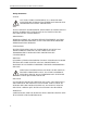
WARNING Disconnect the unit from all power sources before servicing. The unit may be energized from multiple sources. The potential for electric shock exists. WARNING Do not operate with side panel removed. Doing so could result in personal injury. Caution Statements The following equipment cautions appear in the text whenever the equipment is in danger of damage and are repeated here for emphasis. CAUTION Do not block airflow. The air intake vent on the bottom of the load must not be obstructed.
Bird 8930 Series Semiconductor Termaline Coaxial Load Resistor Safety Statements USAGE ANY USE OF THIS INSTRUMENT IN A MANNER NOT SPECIFIED BY THE MANUFACTURER MAY IMPAIR THE INSTRUMENT’S SAFETY PROTECTION. USO EL USO DE ESTE INSTRUMENTO DE MANERA NO ESPECIFICADA POR EL FABRICANTE, PUEDE ANULAR LA PROTECCIÓN DE SEGURIDAD DEL INSTRUMENTO. BENUTZUNG WIRD DAS GERÄT AUF ANDERE WEISE VERWENDET ALS VOM HERSTELLER BESCHRIEBEN, KANN DIE GERÄTESICHERHEIT BEEINTRÄCHTIGT WERDEN.
ZUR VERMEIDUNG GEFÄHRLICHE, ELEKTRISCHE SCHOCKS, SIND WARTUNGSARBEITEN AUSSCHLIEßLICH VON QUALIFIZIERTEM SERVICEPERSONAL DURCHZUFÜHREN. ENTRENTIEN L’EMPLOI DES INSTRUCTIONS D’ENTRETIEN DOIT ÊTRE RÉSERVÉ AU PERSONNEL FORMÉ AUX OPÉRATIONS D’ENTRETIEN. POUR PRÉVENIR UN CHOC ÉLECTRIQUE DANGEREUX, NE PAS EFFECTUER D’ENTRETIEN SI L’ON N’A PAS ÉTÉ QUALIFIÉ POUR CE FAIRE. ASSISTENZA TECNICA LE ISTRUZIONI RELATIVE ALL’ASSISTENZA SONO PREVISTE ESCLUSIVAMENTE PER IL PERSONALE OPPORTUNAMENTE ADDESTRATO.
Bird 8930 Series Semiconductor Termaline Coaxial Load Resistor About This Manual This instruction book covers the models listed below: Connector 115 Vac 230 Vac Female LC 8931-115SC13 8931-230SC13 This instruction book is arranged so that essential information on safety is contained in the front of the book. Reading the Safety Precautions Section before operating the equipment is strongly advised. The remainder of this Instruction Book is divided into Chapters and Sections.
Table of Contents Safety Precautions . . . . . . . . . . . . . . . . . . . . . . . . . . . . i About This Manual. . . . . . . . . . . . . . . . . . . . . . . . . . . . vi Introduction . . . . . . . . . . . . . . . . . . . . . . . . . . . . . . . . 1 Items Supplied . . . . . . . . . . . . . . . . . . . . . . . . . . . . . . . . . . . . . . . . . . . . . . 1 Items Required but not Supplied. . . . . . . . . . . . . . . . . . . . . . . . . . . . . . . . . 1 Optional Accessories. . . . . . . . . . . . . . . . .
Cleaning . . . . . . . . . . . . . . . . . . . . . . . . . . . . . . . . . . . . . . . . . . . . . . . . . . . 13 Inspection . . . . . . . . . . . . . . . . . . . . . . . . . . . . . . . . . . . . . . . . . . . . . . . . . . 13 DC Resistance . . . . . . . . . . . . . . . . . . . . . . . . . . . . . . . . . . . . . . . . . . . . . . 14 Coolant . . . . . . . . . . . . . . . . . . . . . . . . . . . . . . . . . . . . . . . . . . . . . . . . . . . . 15 Repair . . . . . . . . . . . . . . . . . . . . . . . . . . .
Chapter 1 Introduction Bird 8930 Series Semiconductor Loads are general purpose, 50 ohm, coaxial RF transmission line terminations, useful as standby reject loads. They provide accurate, dependable, and low reflection line terminations over a frequency range of dc – 28 MHz, specially calibrated for greater stability at 13.56 MHz. Up to 10,000 watts can be dissipated. The loads have a coolant chamber surrounded by radiator fins.
Bird 8930 Series Semiconductor Termaline Coaxial Load Resistor Figure 1 Bird 8930 Series Outline Drawing (2) VENT PLUGS ONE EACH SIDE 9.5” (241mm) INTERLOCK THERMOSWITCH (OPTIONAL) FAN CONTROL THERMOSWITCH 33-3/8” (847 mm) MANUAL AC ON (4) MTG.
Chapter 2 Load Resistor Coolant Theory of Operation Bird 8930 Loads consist of a thin-film-on-ceramic resistor immersed in a dielectric coolant. The resistor, individually selected for its accuracy, is enclosed in a special housing. When surrounded by the coolant, this produces a uniform, practically reflectionless line termination over the specified frequencies. The load is cooled by forced air and natural fluid convection currents.
Bird 8930 Series Semiconductor Termaline Coaxial Load Resistor Figure 2 Shipping Plug O-ring seal Figure 3 Vent Plug O-ring seal 4
Chapter 3 Installation This chapter provides information for on-site requirements, unpacking, inspection, and preparing the load for use. Unpacking and Inspection 1. Carefully inspect the shipping container for signs of damage. If damage is noticed, do not unpack the unit. Immediately notify the shipping carrier and Bird Electronic Corporation. 2. If the container is not damaged, unpack the unit. Save the packing materials in case the unit should need to be shipped again. 3.
Bird 8930 Series Semiconductor Termaline Coaxial Load Resistor Setup WARNING BOTH vent plugs must be used at all times when the unit is operating or cooling. Failure to do so could result in an explosion or severe burns. y Before first using the load, get a resistance baseline for future maintenance. Refer to “DC Resistance” on page 14 for instructions. y Remove the shipping plugs from the load and replace them with the vent plugs. Refer to Figure 2 and Figure 3 to identify the plugs.
Installation Interlock Connection If installed, connect the optional interlock thermoswitch to the interlock as follows (see Figure 4): CAUTION If installed, connect optional interlock before applying RF power. 1. Unscrew the larger knurled ring-nut (A) at the lower end of the coupling jack assembly. Pull it off the thermoswitch jack (B). Unscrew the small knurled cover fitting (C) from the base plug (D) of the connector to release the base. 2.
Bird 8930 Series Semiconductor Termaline Coaxial Load Resistor AC Power Connection CAUTION Check the local electrical code for proper ac hookup prior to operation of the unit. Make sure the neutral or return hookup is only used for that purpose. WARNING Turn off ac power and RF power when attaching the power cable. The ac power supply required for this unit is 115/230 V, depending on the model, @ 50/60 Hz, 1φ. The blower is equipped with an IEC 320 “cold” (65 °C) ac inlet.
Chapter 4 Operating Instructions CAUTION Maximum power is 2,500 W when the blower is not running. If the indicator light should turn off, immediately reduce RF power to less than 2,500 W. WARNING Never attempt to connect or disconnect RF equipment from the transmission line while RF power is being applied. Leaking RF energy is a potential health hazard.
Bird 8930 Series Semiconductor Termaline Coaxial Load Resistor Shutdown y Turn off RF power at the source. y Wait approximately 15 minutes, or for the fans to stop running. This will allow the load to cool without causing heat stress. y Turn off the blower. Emergency Shutdown Turn off RF power at the source. If the interlock thermoswitch is properly connected, RF power will be automatically turned off when the coolant temperature reaches an unsafe level.
Chapter 5 Maintenance This chapter covers routine maintenance, troubleshooting, specifications, and replacement parts for Bird 8930 Loads. WARNING Disconnect the unit from all power sources before servicing. The unit may be energized from multiple sources. The potential for electric shock exists. WARNING Never attempt to connect or disconnect RF equipment from the transmission line while RF power is being applied. Leaking RF energy is a potential health hazard.
Bird 8930 Series Semiconductor Termaline Coaxial Load Resistor PROBLEM POSSIBLE CAUSE CORRECTION Leaking coolant Loose clamping band Tighten the clamping band Defective or improperly installed O-ring Replace the O-ring (see “Load Resistor” on page 16) Loose RF input connector Tighten connector Faulty RF input connector Replace connector (see “RF Connector” on page 16) Faulty resistor Replace the resistor (see “Load Resistor” on page 16) RF power too high Lower RF power (see “Specifications”
Maintenance Maintenance + Cleaning NOTE: Figure 5 on page 12 shows the location of components which may be referred to in this section. The outside surface of the unit should be wiped free of dust and dirt when necessary. Excessive dust on the cooling fins will interfere with heat dissipation. Clean the RF connector, both metallic and insulating surfaces, with a dry, non-residue forming solvent. WARNING Disconnect the unit from all power sources before servicing.
Bird 8930 Series Semiconductor Termaline Coaxial Load Resistor DC Resistance Measuring the dc resistance between the inner and outer conductors of the RF connector shows changes in the load over time, a good check of the load resistor’s condition. Under normal operating conditions, the resistor should provide at least 5,000 hours of operation before requiring any additional service. DC resistance tracking must start before the load is put into service, and should be measured annually.
Maintenance Coolant Coolant lifetime will vary greatly depending on the operating temperature. For heavy use (full RF power for long times, high ambient temperature, 50 Hz ac supply), check the coolant every 500 hours. If the load has only had light duty (fraction of full power, low ambient temperature, 60 Hz ac supply), then coolant inspection may only be necessary every 2,000 hours. + NOTE: Correct any coolant leakage before inspection.
Bird 8930 Series Semiconductor Termaline Coaxial Load Resistor Repair + NOTE: Figure 5 on page 12 shows the location of components which may be referred to in this section. WARNING Disconnect the unit from all power sources before servicing. The unit may be energized from multiple sources. The potential for electric shock exists. RF Connector The 8931SC13 has a Bird “QC” connector which allows easy changing of the RF connector.
Maintenance Indicator Light WARNING Disconnect the unit from all power sources before servicing. The unit may be energized from multiple sources. The potential for electric shock exists. 1. Remove the four 8-32 pan head screws from the front and back of the base frame. 2. Pull the fan guard straight off the bottom. 3. Remove the quick disconnects on the light and unscrew the retaining sleeve. 4. Remove the light unit. 5. Remove the lens while pressing both locking tabs. 6.
FAN A BLACK TERMINAL STRIP FAN B WHITE BLACK t° FAN C GRN/YEL AC RECEPTACLE N TO CONTROL THERMOSWITCH TOGGLE SWITCH INDICATOR LIGHT WHITE RED t° YELLOW BLACK L YELLOW BLACK INTERLOCK THERMOSWITCH BLACK 18 BLACK FAN CONTROL THERMOSWITCH Bird 8930 Series Semiconductor Termaline Coaxial Load Resistor Figure 7 Wiring Diagram BLACK RED BLUE BLUE RED FRONT
Maintenance Fans When ordering a replacement fan, be sure to specify the model, the fan part number, ac voltage, and fan position. The fan will be provided with lugs and leads of the right length for direct attachment to the terminal block. + NOTE: Different fans are used in the 115V and 230V loads. Also, the fan style depends on its position in the blower; A is in front, B is in the middle, and C is at the rear, nearest the terminal block.
Bird 8930 Series Semiconductor Termaline Coaxial Load Resistor Storage and Shipment Cover the load before storing to keep out dust and dirt. It is not necessary to install the shipping plugs. Store in a dry, dust-free environment where the ambient temperature will remain between –40 and +45 °C (–40 to +113 °F). To ship the load, take the following precautions: y Remove the vent plugs and install the shipping plugs. Wrap the vent plugs with padding and tape them to the side of the load for protection.
Maintenance Specifications Frequency Range dc – 28 MHz Power Rating 10 kW continuous duty Impedance, Nominal 50 ohms VSWR 1.10 max VSWR Stability < 0.1 dB, from 0 to 100% rated power at stability frequency Stability Frequency 13.56 MHz ± 10 kHz Connector “QC” Type, Female LC normally supplied AC Power –115 –230 115 V +10, –6% @ 50/60 Hz ±3% 230 V +10, –6% @ 50/60 Hz ±3% AC Line Power Rating 460 W max Fuse Rating IEC (5 x 20 mm) Type T 115 Vac 230 Vac 3.15 A 1.
Bird 8930 Series Semiconductor Termaline Coaxial Load Resistor Replacement Parts DESCRIPTION QTY PART NUMBER RF Load Resistor 1 8931-117 Resistor O-Ring 1 5-230 Clamping Band Assembly 1 2430-055 Plugs Vent Shipping 2 Interlock Thermoswitch 1 8890-017 Thermoswitch Body 1 8890-015 Thermoswitch Connector Jack 1 2450-018 1 8892-333 Thermoswitch Body 1 8892-334 Thermoswitch Connector Jack 1 2450-018 Coolant, 5 gal (18.
Maintenance Fuse 115 V, 5 x 20 mm Type T, 3.15 A 230 V, 5 x 20 mm Type T, 1.
Limited Warranty All products manufactured by Seller are warranted to be free from defects in material and workmanship for a period of one (1) year, unless otherwise specified, from date of shipment and to conform to applicable specifications, drawings, blueprints and/or samples.