
User's Manual
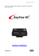


Keyfree RF manual Ver. 2.1
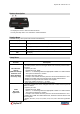
Wire Installation
Black: (-) System Ground Input
This wire should be connected to a ground source. Please ensure that no paint or rust exists on the
surface where the wire will be attached. Also, ensure that the wire is securely fastened to the ground
source.
Red: (+12V) System Power Input
This wire should be connected to a constant +12V.
Main Power should be connected to 1A fuse. (Or connected at the back end of vehicle fuse)
Brown: (-) Unlock Output
This wire provides a negative (-) pulse to unlock the vehicle’s doors. This wire can also be used to
control the Arm Trigger of some aftermarket security products. Please refer to the Installer
Programmable Options for programming details.
Orange: (-) Lock Output
This wire provides a negative (-) pulse to lock the vehicle’s doors. This wire can also be used to
control the Disarm Trigger of some aftermarket security products. Please refer to the Installer
Programmable Options for programming details.
Blue: (-) Aux
This wire provides a negative (-) pulse to supplementary function.
White: (-) Aux
This wire provides a negative (-) pulse to supplementary function.
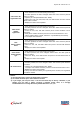
How to programming the options
** Most vehicles do not need to change the Programming.
Function
Description
PulS: Programming of
Pulse duration
(Default: 0.8sec.)
1. Press E button for 2 seconds (setting menu entry)
2. D button pressed, the menu changed. Select the “ PulS” and press the
E button to confirm.
3. Select the Pd08:0.8sec, Pd35: 3.5sec, Pd03: 3sec with D button and
press 2 seconds with E button to end.
4. Display the “donE” and complete.
Lock: Programming of
Lock Pulses
(Default: 1)
1. Press E button for 2 seconds (setting menu entry)
2. D button pressed, the menu changed. Select the “Lock” and press the E
button to confirm.
3. Select the Ln 1, Ln 2, Ln 3, Ln 4, Ln 5 with D button and press 2
seconds with E button to end.
4. Display the “donE” and complete.
* Ln (Lock Pulse Number) 1, 2, 3, 4, 5