Service Manual SRP-350/352plusA&C Thermal Printer Rev. 2.01 http://www.samsungminiprinters.
SRP-350/352plusA&C ■ Table of Contents 1. Precaution Segment .................................................................................................................................... 4 1-1 Safety Precautions................................................................................................................................... 4 1-2 Servicing Precaution................................................................................................................................
SRP-350/352plusA&C 4. Hardware .................................................................................................................................................... 32 4-1 Wiring Diagram ...................................................................................................................................... 32 4-2 Block Diagram........................................................................................................................................
SRP-350/352plusA&C 1. Precaution Segment 1-1 Safety Precautions 1. Be sure that all of the built-in protective devices are replaced. Restore any missing protective shields. 2. When reinstalling the chassis and its assemblies, be sure to restore all protective devices including: nonmetallic control knobs and compartment covers. 3. Make sure that there are no cabinet openings through which people – particularly children - might insert fingers and contact dangerous voltages.
SRP-350/352plusA&C 1-2 Servicing Precaution WARNING 1: First read the Safety Precaution section of this manual. If some unforeseen circumstance creates a conflict between the servicing and safety precautions, always follow the safety precaution. WARNING 2: An electrolytic capacitor installed with the wrong polarity might explode. 1.
SRP-350/352plusA&C 1-3 Precaution for Electrostatically Sensitive Devices (ESDs) 1. Some semiconductor (solid state) devices are easily damaged by static electricity. Such components are called Electrostatically Sensitive Devices (ESDs); examples include integrated circuits and some field-effect transistors. The following techniques will reduce the occurrence of component damaged caused by static electricity. 2.
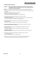
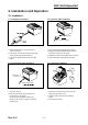
SRP-350/352plusA&C 2. Installation and Operation 2-1 Installation 2-1-1 AC Adapter Installation 2-1-2 Interface Cable Installation Interface Connector Interface Cable Figure 2-1 AC Adapter Installation Figure 2-2 I/F Cable Installation 1. Mack sure the printer is turned off with the side of the switch. 2. Plug the DC cord connector into the power jack on the printer. (Plug the flat side down) 3. Plug the AC Adapter power cord into the wall outlet. 1. Turn off the printer, host ECR and Computer. 2.
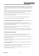
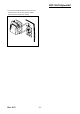
SRP-350/352plusA&C 2-1-5 Wall Mount Installation 1. Remove the three screw from the bottom of The Case lower. Separate the Case lower From the Main body. 2. Attach the Plate-Spring to the right side of Frame-body and tighten a screw as illustrated. 3. After assembling the Case lower to set Body, Turn the Set over and attach the BRKT Hanger To the Case lower then tighten four screws. Rev. 2.01 4. Attach the BRKT Mount to the wall firmly With the eight screws.
SRP-350/352plusA&C 5. Be sure that the BRKT attached properly to match the direction of arrow as follow. and the BRKT Mount should be always fixed vertically. Rev. 2.
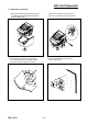
SRP-350/352plusA&C 2-2 Operation 2-2-1 Setting the DIP switches The DIP switches are located on the bottom of the printer. The DIP switches are used to set the printer to perform various functions. Follow these when changing DIP switches setting : 1. 2. 3. 4. Turn the printer power switch off. Remove the screw on the bottom of the printer and open the bracket. Flip the DIP switches using tweezers or another marrow-ended tool. Switches are in when up and off when off down in the Figure 3-12.
SRP-350/352plusA&C 2-2-3 Setting the DIP switch (IEEE1284 Parallel, USB Interface) • DIP Switch 1 SW Function 1-1 Auto Line Feed 1-2 Reserved ~ 1-8 • DIP Switch 2 SW Function 2-1 Reserved 2-2 Internal bell control 2-3 Auto Cutter 2-4 2-5 2-6 2-7 2-8 OFF Disable Default OFF - - OFF OFF Internal bell enable Enable * Offline * Receive Buffer Full Default OFF OFF OFF ON Internal bell disable Disable BUSY Condition Receive Buffer Full Print Density Refer to the following Table 2 Near-End Sensor Stat
SRP-350/352plusA&C 2-2-4 Hexadecimal Dumping This feature allows experienced users to see exactly what data is coming to the printer. This can be useful in finding software problems. when you turn on the hexadecimal dump function, the printer prints all commands and data in hexadecimal format along with a guide section to help you find specific commands. To use the hexadecimal dump function, follow these steps : 1. After you make sure that the printer is off. Open the cover. 2.
SRP-350/352plusA&C ASCII !"#$%&'()*+,-./0123456789:;<=>?@ "#$%&'()*+,-./0123456789:;<=>?@A #$%&'()*+,-./0123456789:;<=>?@AB $%&'()*+,-./0123456789:;<=>?@ABC %&'()*+,-./0123456789:;<=>?@ABCD &'()*+,-./0123456789:;<=>?@ABCDE '()*+,-./0123456789:;<=>?@ABCDEF ()*+,-./0123456789:;<=>?@ABCDEFG ) * + , - . / 0 1 2 3 4 5 67 8 9 : ; < = > ? @ A B C D E F G H *+,-./0123456789:;<=>?@ABCDEFGHI +,-./0123456789:;<=>?@ABCDEFGHIJ , -. /0 1 2 3 4 5 6 7 8 9 : ; < = > ? @ A B C D E F G H I J K -.
SRP-350/352plusA&C 2-2-6 Setting the Memory Switches This printer has Memory Switch set which is software switches. Memory Switch set has MSW1, MSW2,MSW8, MSW9,MSW10,MSW11,Customize value. Memory Switch setting utility can change the Memory Switch set to ON or OFF as shown in the table below (default : all OFF) : Settings of the Memory Switch are stored in the NV memory : therefore, even if the printer is turned off, the settings are maintained.
SRP-350/352plusA&C MSW8 Switch 1~8 Function Reserved ON -- OFF Fixed to OFF MSW9 Switch 1~8 Function Reserved ON -- OFF Fixed to OFF ON OFF External buzzer enable External buzzer disable -2 inch Enable -- Fixed to OFF 3 inch Disable Fixed to OFF ON -- OFF Fixed to OFF MSW10 (Special Function 1) Switch Function 1 External buzzer control (This functions operate only after cutting) 2~4 Reserved 5 Printing width 6 2 Color support 7~8 Reserved MSW11 (Special Function 2) Switch 1~8 Rev. 2.
SRP-350/352plusA&C 3. Product Specifications 3-1 Appearance 3-1-1 Printer Dimensions (mm) SRP-350plus SRP-352plus Figure 3-1 Printer Dimension 3-1-2 AC Adapter Dimensions (mm) 35mm 115mm 65mm Figure 3-2 Adapter Dimension Rev. 2.
SRP-350/352plusA&C 3-1-3 Feature Locations-SRP-350/352plusA/C TYPE 1. 2. 3. 4. 5. 6. 7. Cover-Open Case-Upper Case-Lower Label-Control Push Button Cover-Cutter Power Button Rev. 2.01 8. Bracket Dip Switch 9a. Parallel interface(IEEE-1284) 9b. Serial interface(RS-232C) 9c. Ethernet interface(10BASE T) 9d. 10. DC Power Jack 11. Drawer Kick-Out Connector 12. USB 2.
SRP-350/352plusA&C 3-2 General Specifications Item Product Processor Memory Interface Serial (RS-232C / RS-485) Interface Parallel USB USB2.0 Printer Auto Cutter Power Consumption AC Adapter Environment Condition Weight Dimensions(mm) Rev. 2.
SRP-350/352plusA&C 3-3 Thermal Printer Specifications 3-3-1 Printer Specification 1) 180dpi Item Description Model • SRP-350plusA/C(TPH : AG072-H7E817,AOI Electronoics) Print Method • Thermal Line Printing Dot Density • 0.141 mm (7.09 Dots/mm) Printing Direction • Unidirection with friction feed Printing Width • 72±0.2mm, 512 dot Position Character / Line • 42 (Font A : 12x24) Character Spacing • 0.28mm (0.01) (2 dots) (Font A) • 0.28mm (0.01) (2 dots) (Font B) Printing Speed • Mono Max.
SRP-350/352plusA&C 3-3-3 Paper Specification Item Description Paper Type • Mono :TF50KS-E(Nippon paper) • 2Color : PB-70(Mitsubishi) Paper Form • Paper Roll Paper Width • 80mm(+0,-0.5) Paper Roll Size • Max 83mm(3.26”) Spool Inside Dia. • 12mm (0.47) Spool Outside Dia. • 18mm (0.71) Remark Table 3-5 Thermal Printer Paper Specification ※ Note * Mono : The Following paper can be used instead of the specified paper above. TF50KS-E(Paper thickness : 65μm) : Nippon Paper industries Co., Ltd.
SRP-350/352plusA&C 3-3-5 Printable Area a b d c e Figure 3-4 Printable Area 1) 180dpi Item Description 80±0.5mm(3.15 ±0.0197) a 0.141 (0.0056 ) b 72±0.2mm(2.83 ±0.0079) c 2.75mm~4.25mm d 2.75mm~4.25mm e 512 Dots 56 Character Font 9X24 42 Character Font 12X24 * ‘d’ & ‘e’ position can be shifted while printing according to the paper position. Remark 2) 203dpi Item Description 80±0.5mm(3.15 ±0.0197) a 0.125 (0.0049 ) b 72mm±0.2mm (2.83±0.0079) c 2.75mm~4.25mm d 2.75mm~4.
SRP-350/352plusA&C Item Maximum Unit Print Cycle (S.L.T.) 0.71 ml/Line Supply Energy 0.44 mJ/Dot Supply Voltage 26.4 Substrate Temperature 70 V ℃ Number of heating dots at same time 256 Dots Logic Supply Voltage (Vdd) 5.25 V Logic input Voltage (Vin) Conditions Tsub=25℃ Vp < 28.0V (Vp : Peak of VH) Thermister Temperature Include Peak Voltage of Vdd -0.5 ~ Vdd+0.
SRP-350/352plusA&C 3-4 SMPS Specifications 3-4-1 SMPS (Switching Mode Power Supply) Specification Item Input Voltage Input Current In rush Current Line Regulation Load Regulation Ripple Noise O.C.P (Over Current Protect) S.C.P (Shot Current Protect) Description • Typical : 100V ~ 240V AC • Min : 90V AC • Max : 264V ac • Max : 1.5A (When 120V), 0.75A (When 230V) • Max : 40A (Peak to Peak) • +24V 1% • +24V 5% • Peak 300mV • 3.0A ~ 8.
SRP-350/352plusA&C 3-5 Interface Specifications 3-5-1 RS-232C Serial Interface 3-5-1(a) Specification Item Data Transmission Synchronization HandShaking (Flow Control) Signal Level Baud Rate Data Word Length Parity Connector Description • Serial • Asynchronous • H/W : DTR/DSR • S/W : XON/XOFF • Logic1 (MARK) : -3V ~ -15V • Logic0 (SPACE) : +3V ~ +15V • 2400/4800/9600/19200/38400/57600/115200 Bps • 8 bit • None • DB25P Female (I/F PBA) Table 3-14 RS-232C Specification Remark XON : ASC Code 11h XOFF:ASC Co
SRP-350/352plusA&C 3-5-1(c) Cable Connection (S.G) 1 1 (S.G) (TXD) 2 2 (TXD) (RXD) 3 3 (RXD) Printer Host Side(25P) Side(25P) (DSR) 6 6 (DSR) (DTR) 20 20 (DTR) (S.G) 7 7 (S.G) Figure 3-7 RS-232C Cable Connection 3-5-1(d) Signal Description Pin No. BODY 2 3 Signal Name Frame GND TXD RXD 6 DSR 7 Signal GND 20 DTR Rev. 2.01 Signal Direction Output Input Function Frame Ground Transmit Data Receive Data This signal indicates whether the host computer can receive data.
SRP-350/352plusA&C 3-5-1(e) H/W Flow Control When DTR/DSR flow control is select, before transmitting a data, the Printer checks whether the host is BUSY or not. If the host is BUSY, the Printer does not transmit a data to the host. If the host is not BUSY, the Printer transmits a data to the Host. The host is the same. Refer to the Interface Part of Chapter 7 (Special Circuit Diagrams).
SRP-350/352plusA&C 3-5-2(c) Signal Specification (Compatibility/Nibble/Byte mode) Pin No.
SRP-350/352plusA&C 3-5-3 USB2.0 Interface SRP-350plus support the USB (Universal Serial Bus) Serial Communication. 3-5-3(a) Specification Item Transfer Type Data Signal Data Format Transceiver Speed Power Cable & Connector Other Description • BULK • Bi-direction, Half-Duplex • Differential Signal Pair (D+ / D-) • NRZI Format • Zero Bit Stuffing after 6 ones • Differential Receive Sensitivity : 200[mV] • Differential common Mode Range : 0.8 ~ 2.5[V] • Single-End Receiver Threshold : 0.8 ~ 2.
SRP-350/352plusA&C Figure 3-9 USB Cable 3-5-4(d) Construction Raw materials used in the fabrication of this cable must be of such quality that the fabricated cable is capable of meeting or exceeding the mechanical and electrical performance criteria of the most current USB Specification revision and all applicable domestic and international safety/testing agency requirements; e.g., UL, CSA, BSA, NEC, etc., for electronic signaling and power distribution cables in its category.
SRP-350/352plusA&C ※ Note: Minimum conductor construction must be stranded tinned copper. To minimize end user termination problems, USB uses a keyed connector protocol. The physical difference in the Series A and B connectors insures proper end user connectivity. The A connector is the principle means of connecting USB devices directly to a host or to the downstream port of a hub. All USB devices must have the standard Series A connector specified in this chapter.
SRP-350/352plusA&C 3-6 Cash Drawer Specifications 3-6-1 Drawer Cable Ferrite Core : 1 turn (OP-18E : 18.2 x 12.5 x 25.5) Figure 3-11 Drawer Cable 3-6-2 Cable Connection Pin No. 1 2 3 4 5 6 Description Frame GND Drawer Kick-Out Driver Signal #1 Drawer Open / Close Signal +24V Drawer Kick-Out Driver Signal #2 Signal GND Table 3-21 Drawer Cable Connection ※ Note : +24V is always output through pin 4 during power on. Rev. 2.
SRP-350/352plusA&C 4.
SRP-350/352plusA&C 4-2 Block Diagram POWER ADAPTER +24VDC POWER SUPPLY CIRCUIT VPP(+24V) VTH(+24V) VCC(+5V) +3.3V +3.3V RS-232 DRIVER RS-232 CON. IEEE-1284 DRIVER IEEE-1284 CON. ETHERNET DRIVER ETHERNET CON USB2.0 DRIVER USB CON. SENSOR CIRCUIT P_END & NEAR SENSOR RESET CIRCUIT +2.
SRP-350/352plusA&C 4-3 Special Circuit Descriptions 4-3-1 Power Circuit This system is operated under 100Vac or 240Vac. The power circuit supplies the three differential DC voltage sources. [Figure 4-3 Power Block Diagram] No. 1 2 3 4 5 6 VOLTAGE VPP(+24VDC) VTH(+24VDC) Vdw(+7.8VDC) Vcc(+5VDC) Vdd(+3.3VDC) Vdd(+2.
SRP-350/352plusA&C 4-3-2 RESET Circuit Reset signal is signal in order to start-up CPU under Power-on. Reset circuit uses a reset ASM811REUSF-T(U8). When 3.3Vdc is fallen under 2.7Vdc by Power-off, reset signal prohibits the system from miss-operating by lowering down to 0V. ASM811 REUSF-T [Figure 4-4 Reset Block Diagram] [Figure 4-5 Reset Waveform] Rev. 2.
SRP-350/352plusA&C 4-3-3 Buzzer and Cash Drawer Circuits 1) Buzzer Driving Circuit The Buzzer is used to inform several kinds of states which occur under system operating and gives some information to users by controlling the P86 of CPU (UPD70F3107) [Figure 4-6 Buzzer Block Diagram] 2) Cash Drawer Driving Circuit The circuit is used for opening cash drawer and driven by the Q10, Q11(2SD2170). When its state is high level signal, Q10 or Q11 (2SD2170) drive the solenoid to open the cash drawer.
SRP-350/352plusA&C 4-3-4 I/F PBA Detect Block Diagram When the printer is ON, the printer checks what kind of the I/F PBA is installed. After detection, the CPU specify the I/O port properly. The following is the method of I/F PBA detection. The I/F PBA has the three return Signal (MD0~2). The CPU recognize the I/F PBA by the value of the three return signal. I/F PBA RS-232C IEEE1284 USB2.
SRP-350/352plusA&C 4-3-6 Parallel Communication Block Diagram The printer support the bidirectional Parallel Interface with Centronics, Nibble, Byte Mode. The Centronics is Forward and the Nibble, Byte are reverse Mode. [Figure 4-10 IEEE1284 Communication Block Diagram] 4-3-7 USB Communication Block Diagram The printer support the USB (Universal Serial Bus). The transfer type of the printer is the BULK. [Figure 4-11 USB2.0 Communication Block Diagram] Rev. 2.
SRP-350/352plusA&C 4-3-8 DIP Switch Circuit The key board circuit consist of the scan signal of 3 lines and the return signal of 2-line. The CPU sends repeatedly and continuously the scan data DIP_A~DIP. The DIP S/W information input in the return signal if the specific DIP S/W is ON status during the given time. The CPU reads the data through DIP IN1~IN2 and analyzes what DIP S/W is ON and performs the selected function.
SRP-350/352plusA&C 4-3-9 Thermal Printer Head Circuit First, the CPU sends a Serial Clock and Serial Data 256Bits(32Bytes) to the Shift Register of the Thermal Printer. The Serial Data are stored to each Shift Register in the Thermal Printer. Because the Data#1 Pin and the Data#2 pin are shorted on Main PCB, the Data(256Bits) are stored in both Shift Register#1 and #2. Second, the CPU send a Latch Signal to the Thermal Printer.
SRP-350/352plusA&C 5. Disassembly and Assembly 5-1 Case lower block 1.Remove the three screw. 1 Scrw (3x8) 2.Sparate the BRKT Dip switch, 2 Brkt Dip Switch 4 Foot Rubber Case lower, Foot-Rubber from the Printer. 3 Case Lower 1.Remove the connector wires from main PBA and sub Assembly. Rev. 2.
SRP-350/352plusA&C 8 Screw 1.Remove the Screws form the BRKT PBA. 2.Separate the BRKT Interface. 1 Screw (3x6) 2 Brkt PCB Screw 8 4 Screw 3.Remove the two screws. 4.Separate the BRKT Interface from the I/F PBA Assembly. 5.Separate the I/F PBA from the Main PBA. 6.Remove the four screws. 6 Main PCB 7.Seperate the Main PBA form the 3 Brkt Serial (Parallel, 485) BRKT PCB. 5 PCB Serial (Parallel, 485) 7 Screw (3x6) 1.Separate the Cover cable from 1 Case Lower 2 Cover Cabel Rev. 2.
SRP-350/352plusA&C 5-2 Case Upper block 1.Push the button to open the Cove Open. 2.Remove the four screws. 3.Separate the Cover open. 4.Separate the Cover cutter. 5.Remove the screws. 1.Remove the two screws. 2.Lift the Case upper in the direction of an arrow during pushing the Push button. 3.Remove the three screws. 4.Separate the Manual cutter from the Case upper. Rev. 2.
SRP-350/352plusA&C 1.Remove the E-Ring. 2.Separate the Spring tension, the Shaft hinge and the E-Ring. 3.Remove the E-Ring. 4.Separate the Bushing and the Roller Platen Assembly. 1 Spring Hook 1.Remove the Spring Hook, two screws. 2.Separate the BRKT Hook. 2 4 Brkt-Hook 3 Screw (3x4.4) Rev. 2.
SRP-350/352plusA&C 1 Screw (3x4) 7 Cover Plate 2 Fixed Cutter 1.Remove the three screws. 2.Separate the Fixed-cutter from the Cover Housing. 3.Remove the two screws. 4.Separate the Cutter Blade from Fixed-cutter. 5 Cutter Blade 3 Cover Housing 5.Remove the two screws. 6.Separate the Cover plate from the Cover housing. 4 Screw (3x4) 6 Screw (3x6) 5-3 Frame block 1.Remove the two screws. 2.Separate the Black Auto cutter from the Frame main. Rev. 2.
SRP-350/352plusA&C 1.Remove the screw. 2.Push the Heat-sink Assembly in the direction of an arrow and Separate it. 2 Heatsink Assy 1 Screw 1.Remove the screw. 2.Separate the Plate-ground and 3 Brkt TPH Rear 6 Heat Sink BRKT TPH Rear. 3.Remover the two screws. 4.Separate the Heat-sink and the 2 Plate ground Spring TPH. 5.Separate the Connector from the Heat-sink. 5 Spring TPH 1 Screw (3x4) 4 Screw (3x4) 7 Rev. 2.
SRP-350/352plusA&C 1 Screw (3x8) 1.Remove the two screws. 2.Separate the Frame Main from the 2 Frame Main BRKT PCB. 3.Separate the Power Switch from the BRKT PCB. 3 Brkt PCB 4 Power Switch 1.Remove the screw, And separate the 3 Frame Main 13 14 5 Control board from the Frame Main. Plate-Spring 2.Remover the Washer slip. 3.Separate the Lever Release from Screw (3x8) the Frame Main. Lever Release 2 4.Remove the two screws. Control Board 5.Separate the Button Assembly from the Frame Main. 6.
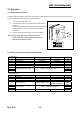
SRP-350/352plusA&C 6. Adjustments and Maintenance 6-1 Adjustment 6-1-1 Remaining Roll Paper Adjustment This sensor is set to the step3 position at the factory. If you find that there is not or too enough paper remaining on the roll when the near-end sensor is triggered, you can change the setting to the upper or Lower position as described below. Note : The factory setting is based on a paper roll core with an outside diameter of 18mm.
SRP-350/352plusA&C 6-1-2 Paper Jam If the paper jam occur, the Buzzer will beep. If the cover-open can be opened, open the Cover-open and remove the paper. If the Cover-open can not be opened, Follow the below. 1. Turn the printer on to make the cutter initialized, and then open the cover-open. 2. In case that the cutter is not initialized, remove the cover-cutter then remove the paper jam with turning the knob to the arrow direction as shown below picture.
SRP-350/352plusA&C 6-2 Maintenance Paper dust in the heating elements may lower the print quality. In this case, clean the print head as follow; ※ Caution: Turn off the printer power before cleaning. ※ Caution: Note that the thermal head (Thermal element and Radiation plate) becomes very hot during normal operation, creating the danger of burn injury. Be sure to wait for about 10 minutes after turning printer power off before beginning the cleaning. 1. Open the cover-open. 2.
SRP-350/352plusA&C 7. Troubleshooting This chapter describes the methods for troubleshooting in this Receipt Printer. 7-1 Power Problem Power Problem Power Out Ok? On SMPS N 1. Check the Input/Output Power Cable 2. Replace the Adapter(SMPS) Y Power VDR (+24V) Ok? N Y Power VTPH (+24V) Ok? 1. Check the Harness of Power S/W 2. Check the related Circuit & Pattern N Y Power (+7.8V) Ok? 1. Check the TR (Q3,Q4) 2. Check the related Circuit & Pattern N Y Power VCC (+5V) Ok? 1.
SRP-350/352plusA&C 7-2 System Problem System Problem Reset Signal Ok? N 1. Check the IC (U8,ASM811REUSF-T) 2. Check the Reset Pin on Flash Memory and CPU 3. Check the related Circuit & Pattern on PCB Y Clock Signal Ok? N 1. Check the Frequency (5MHz) 2. Check the related Circuit & Pattern on PCB Y Program Ok? N 1. Check the Address/Data Line Pattern 2. Check the related Circuit & Pattern on PCB 3. Program download again Y SRAM Ok? N 1. Check the /CS Signal 2. Check the SRAM 3.
SRP-350/352plusA&C 7-3 Panel PBA and Sensor Problem Panel PBA Problem LED Ok? N Y Feed S/W Ok? N 1. Check the Feed S/W Signal on Main PBA 2. Check the Harness 3. Check the related Circuit ,Pattern & Component Y Cover Open S/W Ok? 1. Check the LED Signal from CPU on Main PBA 2. Check the Harness (Signal, VCC, GND) 3. Check the related Circuit, Pattern & Component 4. Replace the Panel PBA N 1. Check the Cover S/W Signal on Main PBA 2. Check the Harness 3.
SRP-350/352plusA&C 7-4 Thermal Printer Head and Feed Motor Problem Thermal Printer Head Problem Control Signal Ok? N 1. Check the Control Signal on CPU (Data / CLK / Latch / Strobe 1, Strobe 2) 2. Check the Harness 3. Check the related Circuit & Pattern Y Power VCC VTPH Ok? N 1. Refer to the Power Problem 2. Check the Harness Y End Feed Motor Problem Feed Motor Ok? Y N 1. Check the Signal (MOT_PHA1,MOT_PHA2) on CPU 2.
SRP-350/352plusA&C 7-5 Auto Cutter and Drawer Problem Auto Cutter Problem Auto Cutter OK? N 1. 2. 3. 4. Y Auto Cutter S/W Ok? Check the Signal on CPU Check the Output Signal of U13 (TA8428K) Check the Harness Check the Auto Cutter Assembly (Motor, Cutter...) N 1. Check the Signal on CPU 2. Check the Harness 3. Check the Micro S/W in the Auto Cutter Assembly Y End Drawer Problem Drawer Open Failure? Y 1. Check the Drawer Connector & Harness 2. Check the Drawer Signals on CPU (P33, P34) 3.
SRP-350/352plusA&C 7-6 Dip S/W and I/F PBA Select Problem Dip Switch Problem Dip S/W Input Ok? N Y 1. Check the Output Signal (DIP_A~C) 2. Check the Input Signal (DIP_IN1~IN2) 3. Check the related Circuit & Pattern End I/F PBA Select Problem I/F PBA Select Ok? Y N 1. Check the Diode on I/F PBA 2. Check the Input Signal (MD0*~MD2*) 3. Check the related Circuit & Pattern End Rev. 2.
SRP-350/352plusA&C 7-7 RS-232C Serial Communication Problem RS-232C Problem Communication Failure? Y N H/W Handshake Y 1. Check the connection of the RS-232C Connector and Other side 2. Check the I/F Cable whether it is open or short 3. Check the Txd, Rxd Pin on CPU 4. Check the MAX232 Driving Chip and related Circuit on I/F PBA 5. Check whether Signal is affected by the Cable Noise N 1. Check the connection of the H/W handshaking Line and Other side (DTR/DSR) 2.
SRP-350/352plusA&C 7-8 IEEE-1284 Parallel Communication Problem IEEE-1284 Problem Forward Mode Failure? N Y 1. 2. 3. 4. 5. Check the Control Line (/CS_P) Check the 1284 Control Line and Status Line Check the Signal of ICs (U1,U3,U4,U5) Check the 1284 Cable whether it is open or shot Check the related Circuit & Pattern on I/F PBA End Rev. 2.
SRP-350/352plusA&C 7-9 USB2.0 Communication Problem USB Problem Main PBA I/F Failure? Y N Reverse Mode Failure? N 1. Check the Control Line & Signal (/CS_U,/RD,/LWR,USB_/IRQ) 2. Check the Data Line and Signal 3. Check the Connector (34P) 4. Check the Clock (30MHz) 5. Check the related Circuit & Pattern on Main PBA Y 1. 2. 3. 4. Check the Clock (30MHz) Check the Host whether it works correctly Check the USB Cable whether it is open or shot Check the related Circuit & Pattern on Main PBA End Rev.