User’s Manual SRP-270 Impact Printer Rev. 1.05 http://www.bixolon.
SRP-270 ■ Table of Contents ※ Manual Information & Usage Precautions................................................................3 1. Content Confirmation ..................................................................................................7 2. Product Part Names.....................................................................................................8 3. Installation & Usage.....................................................................................................
SRP-270 ■ Manual Information ※ Manual Information & Usage Precautions This user manual contains basic information for product usage as well as for emergency measures that may be required. ※ The following separate manuals provide more detailed content on various technological issues and areas. 1. Windows Driver Manual This manual provides information on installation and main functions of the Windows Driver for this product. 2.
SRP-270 ■ Safety Precautions In using the present appliance, please keep the following safety regulations in order to prevent any hazard or material damage. WARNING Violating following instructions can cause serious injury or death. Do not plug several products in one multi-outlet. • • • • You must use only the supplied adapter. This can provoke over-heating and a fire. If the plug is wet or dirty, dry or wipe it before usage. If the plug does not fit perfectly with the outlet, do not plug in.
SRP-270 CAUTION Violating following instructions can cause slight wound or damage the appliance. If you observe a strange smoke, odor or noise from the printer, unplug it before taking following measures. Keep the desiccant out of children’s reach. • If not, they may eat it. • Switch off the printer and unplug the set from the mains. • After the disappearance of the smoke, call your dealer to repair it. TO UNPLUG PROHIBIT PRINTER Install the printer on the stable surface.
SRP-270 ■ Other Precautions The copyright for this user manual and various other manuals is property of the BIXOLON Co., Ltd. Any copying or conversion into electronic firm and saving of this material without the express written permission of BIXOLON Co., Ltd. is strictly prohibited. Use of the information contained in this manual is not subject to any patent liability. This manual has been prepared with utmost care and attention to detail but may contain certain errors and/or omissions. BIXOLON Co., Ltd.
SRP-270 1. Content Confirmation The following items should all be contained in the printer package. Contact the dealer from which the purchase was made if any item is damaged and/or missing. SRP-270A SRP-270C SRP-270D Power Cord AC Adapter Paper Roll Ribbon Cartridge Installation Guide CD SRP-270D Exclusive Spool Rev. 1.
SRP-270 2. Product Part Names Cartridge Knob Printer Cover Spool Ribbon Cartridge Auto Cutter Paper Feed Button Power Switch Rev. 1.
SRP-270 3. Installation & Usage 3-1 Power Connection Connect power to the printer as shown below. AC Adapter Power Cord Power Connector 1) Turn off the printer power switch. 2) Check to see that the AC adapter voltage matches that of the power source. 3) Connect the AC adapter jack to the printer power connector. 4) Connect the power cord to the AC adapter. 5) Connect the power cord to a power source/outlet. Rev. 1.
SRP-270 3-2 Interface Cable Connection Connect the printer with a POS system (PC, ECR, etc.) via an interface cable as shown below. This printer supports the following communications interface standards. - RS-232C (Serial) RS-485 (Serial) IEEE1284 (Parallel) USB Interface Connector Interface Cable 1) Turn off the power switch on both the printer and the POS system (PC, ECR, etc.). 2) Connect the interface cable to the printer interface connector.
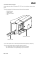
SRP-270 3-3 Cash Drawer Connection Connect the printer and cash drawer via the interface cable as shown below. Cash Drawer Connector Cash Drawer Cable 1) Turn off the power switch on both the printer and the POS system (PC, ECR, etc.). 2) Connect the cash drawer cable to the printer cash drawer connector. ※ CAUTION Do not connect a telephone line to the printer cash drawer connector. Doing so may cause damage to the printer and telephone line. Rev. 1.
SRP-270 3-4 Ribbon Cartridge Installation Install the ribbon cartridge as shown below. Printer Cover Cartridge Knob Ribbon Cartridge Auto Cutter 1) Turn off the printer power switch. 2) Open the printer cover. 3) Before inserting the ribbon cartridge, turn the cartridge knob clockwise in order prevent the ribbon from tangling. 4) Insert the ribbon cartridge as shown in the image above, and set the ribbon so that is behind the printer head.
SRP-270 3-5 Paper Installation The paper used varies by printer model. - SRP-270 A/C: 1-layer paper - SRP-270 D: 2-layer paper 3-5-1 SRP-270 A/C Model 1) Turn on the printer power. 2) Open the printer cover. (Remove any core of a fully used paper roll if present.) 3) Undo the paper roll, and make sure that the lower edge is cleanly cut. 4) Insert the paper roll as shown below. Rev. 1.
SRP-270 5) Insert the end of the paper roll into the paper slot as shown below. The paper then feeds automatically. Automatic cutting is available for printer models equipped with auto cutters. (SRP-270C) - For printer models without auto cutters, tear off the paper as shown below. (SRP-270A) Rev. 1.
SRP-270 3-5-2 SRP-270 D Model 1) Turn on the printer power. 2) Open the printer cover. (Remove any core of a fully used paper roll if present.) 3) Undo the paper roll, and make sure that the lower edge is cleanly cut. 4) Insert the paper roll as shown below. (Exercise special care to align the paper direction correctly.) Rev. 1.
SRP-270 5) Insert the end of the paper roll into the paper slot as shown below. The paper then feeds automatically. 6) Turn the spool and insert the paper into the groove. several times, and then affix into the spool slot. Spool Rev. 1.
SRP-270 7) Tear off any extruding paper. 8) Close the auto cutter, and then close the printer cover. Spool Auto Cutter Spool Paper Roll Auto Cutter (Correct Paper Installation) Rev. 1.
SRP-270 3-6 Control Panel Usage O Feed Press this button to feed paper. This button is also used for self-tests and hexa-printing. - Refer to “4. Self-Test” for details related to self-tests. - Refer to the service manual for information on hexa-printing. O Power This lamp turns green when the printer power is on. O Error This lamp turns red when a printer error occurs. O Paper Out This lamp turns red when paper has been fully used. Rev. 1.
SRP-270 4. Self-Test Run the self-test when first setting the printer or when encountering a problem. following printer attributes can be assessed. The - Control Circuits, Mechanisms, Print Quality, and ROM Version If no issue is found with the printer after running the self-test, examine the other devices or peripherals and software. This function is independent of such other devices and software. Self-Test instructions are as follows. 1) Check to see that the paper is properly installed.
SRP-270 5. Fine Tuning 5-1 Dip Switch Adjustment The dip switches can be used to select the following printer functions. - Emulation - Auto Cutter, Font Interval, Auto Line Feed - Serial Communications Settings, Hexa-Printing The dip switches are located on the under side of the printer. Dip switch adjustment instructions are as follows. 1) Turn off the printer power. 2) Turn the printer over and remove the dip switch cover. 3) Use a pointy edged object to adjust the dip switches.
SRP-270 [Diagram 1] Switch Functions When Using a Serial Interface (RS232C & RS485) [Dip Switch 1 Settings] Switch Function SW1-1 SW1-2 On Emulation Selection Off Refer to Chart (1) below.
SRP-270 [Diagram 2] Switch Functions When Using a Parallel or USB Interface [Dip Switch 1 Settings] Switch Function SW1-1 SW1-2 On Emulation Selection Off Refer to Chart (1) below.
SRP-270 5-2 Paper Jam Removal Remove jammed paper as shown below. Printer Cover Ribbon Cartridge Coin Lock Mechanism Handle Head Cover Manual Screw Auto Cutter Paper Jam 1) Open the printer cover. 2) Lift the lock mechanism handle and raise the auto cutter. 3) Remove the ribbon cartridge. 4) Use a screwdriver or coin to loosen the manual screw as shown above. 5) Remove the head cover. Rev. 1.
SRP-270 Paper Jam Head Paper Feed Knob 6) Push the head to the left and fix in place. 7) Turn the paper feed knob and remove the jammed paper. 8) Replace the head cover and fasten the screw. 9) Place the ribbon cartridge and paper back in their original positions and close the printer cover. ※ WARNING The printer head can get hot during printing. After printing, wait at least 10 minutes to allow cooling before handling the printer interior. Rev. 1.
SRP-270 ※ CAUTION If the cutting edge of the auto cutter is not in its normal position, paper cannot be inserted properly. Insert a screwdriver into the hole near the bottom of the auto cutter as shown below, and turn the gear within the auto cutter to adjust the cutting edge to its normal position. [Cutting Edge Position] Normal Position Rev. 1.
SRP-270 6. Appendix 6-1 Specifications Printer Ribbon Item Printing Method Head Pin Number Print Direction Print Speed Characters Per Line Type Color Life Paper Adapter Auto Cutter Type Width Diameter Thickness SMPS AC Input SMPS Voltage, Current Cutter Type Cutter Width Cutter Thickness Total Volume Other Weight Reliability Operation Temperature Operation Humidity Storage Temperature Storage Humidity Rev. 1.05 Description Serial Impact Dot 9 Two-way 4.
SRP-270 6-2 RS-232C (Serial Interface) Cable Specifications 1) Printer Rear Image Cash Drawer Connector Serial Interface Power Connector ※ Turning the dip switch on the Serial interface to the ON position connects DTR and RTS signals together. 2) Cable Specifications Printer Side (25P) (Shield.G) (S.GND) Printer Side (25P) (Shield.G) (Shield.G) (S.GND) Pin No. 1 2 3 4 5 6 7 20 Rev. 1.05 Host Side (25P) Signal FG TxD RxD RTS CTS DSR SG DTR (S.
SRP-270 6-3 RS-485 (Serial Interface) Cable Specifications 1) Printer Rear Image Cash Drawer Connector Serial Interface Power Connector 2) Cable Specifications Host Side Printer Side Pin No. 1 2 3 4 5 7 8 9 10 11 Rev. 1.
SRP-270 6-4 IEEE1284 (Parallel Interface) Cable Specifications 1) Printer Rear Image Cash Drawer Connector Parallel Interface Power Connector 2) Cable Specifications Pin No. 1 2 3 4 5 6 7 8 9 10 11 12 13 14 15 16 17 18 19~30 31 32 33 34 35 36 Source Host Host / Printer Host / Printer Host / Printer Host / Printer Host / Printer Host / Printer Host / Printer Host / Printer Printer Printer Printer Printer Host Printer Host Printer Printer Printer Host Rev. 1.
SRP-270 6-5 USB Interface Cable Specifications 1) Printer Rear Image Cash Drawer Connector USB Interface Power Connector 2) Cable Specifications Pin No. 1 2 3 4 Shell Signal VBUS DD+ GND Shield Wire Color Red White Green Black Drain Wire Function Host Power Data (D-) Data (D+) Signal Ground Frame Ground 6-6 Cash Drawer Cable Specifications Pin No.
SRP-270 6-7 Certification 1) EMC & Safety Standards • Europe: CE EMC,CB-Scheme:IEC60950-1, GS: EN60950-1: 2001 • North America: FCC rules parts 15B WARNING Use of an unprotected interface cable with this printer conflicts with EMC standards. Users should only use cables approved by BIXOLON.