Service Manual SRP-270 Impact Printer Rev. 3.02 http://www.samsungminiprinters.
SRP-270 ■ Table of Contents 1. Precaution Segment .................................................................................................................................... 6 1-1 Safety Precautions................................................................................................................................... 6 1-2 Servicing Precaution................................................................................................................................
SRP-270 4. Hardware .................................................................................................................................................... 29 4-1 Wiring Diagram ...................................................................................................................................... 29 4-2 Block Diagram........................................................................................................................................
SRP-270 8-2 Handling the Printer ............................................................................................................................... 61 8-2-1 Precautions on Printer Handling ..................................................................................................... 61 8-2-2 Paper Setting Procedures (Insertion/Removal) .............................................................................. 62 8-2-3 Ribbon Cassette Installation .....................................
SRP-270 ■ About About this Manual This Service Manual describes how to perform hardware service maintenance for the BIXOLON SRP-270 Receipt Printer. Notes Notes may appear anywhere in the manual. They draw your attention to additional information about the item. Precaution symbols Indicates a Safety Precaution that applies to this part component. Indicates the part or component is an electro-statically sensitive device. Use caution when handling these parts. Copyright ⓒ 2008 by BIXOLON Co., Ltd.
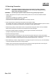
SRP-270 1. Precaution Segment Follow these safety, servicing and ESD precautions to prevent damage and to protect against potential hazards such as electrical shock. 1-1 Safety Precautions 1. Be sure that all of the built-in protective devices are replaced. Restore any missing protective shields. 2. When reinstalling the chassis and its assemblies, be sure to restore all protective devices, including nonmetallic control knobs and compartment covers. 3.
SRP-270 1-2 Servicing Precaution WARNING 1: First read the Safety Precaution section of this manual. If some unforeseen circumstance creates a conflict between the servicing and safety precautions, always follow the safety precaution. WARNING 2: An electrolytic capacitor installed with the wrong polarity might explode. 1.
SRP-270 1-3 Precaution for Electrostatically Sensitive Devices (ESDs) 1. Some semiconductor (solid state) devices are easily damaged by static electricity. Such components are called Electrostatically Sensitive Devices (ESDs); examples include integrated circuits and some fieldeffect transistors. The following techniques will reduce the occurrence of component damaged caused by static electricity. 2.
SRP-270 2. Installation and Operation 2-1 Installation 2-1-1 AC Adapter Installation 2-1-2 Interface Cable Installation 1. Mack sure the printer is turned off with the “Off” side of the switch is pressed down. 2. Check the label on the AC Adapter to make sure the voltage required by the AC Adapter matches that of the electrical outlet. 3. Plug the DC cord connector into the power jack on the printer. 4. Plug the AC Adapter power cord into the wall outlet. 1. Turn off the printer, host ECR and Computer.
SRP-270 2-1-5 Paper Roll Installation 6. If the paper is loose, wind the Rewind Spindle to tighten the paper. 1. Using a new roll paper, unroll the paper and cut the end as shown. 7. Release the holder after fitting the Roll Paper Core onto the Holder. Make sure to load the paper roll so that it rotates in the correct direction. 2. In case of Model 270C/D, open Auto Cutter on the power ON. 3. Auto feeding one paper. 4.
SRP-270 2-2 Operation 2-2-1 Setting the DIP switches The DIP switches are located on the bottom of the printer. The DIP switches are used to set the printer to perform various functions. Follow these when changing DIP switches setting : 1. 2. 3. 4. Turn the printer power switch off. Remove the screw on the bottom of the printer and open the bracket. Flip the DIP switches using tweezers or another narrowended tool. Switches are on when up and off when off down.
SRP-270 2-2-3 Setting the DIP switch (IEEE1284 Parallel, USB Interface) • DIP Switch 1 SW 1 2 3 4 5 6 7 8 • DIP Switch 2 SW 1 FUNCTION Emulation Selection OFF Refer to the following Table 1 Auto-Cutter FONT SPACE Enable 2 Disable 3 Korean Type Selection Unified Complete FUNCTION ON Always Enabled YES - OFF Always Disabled NO - Function for Service Engineer Auto Line Feed 2 3 4 5 6 7 8 Hex Dump Reserved Reserved Reserved Reserved Reserved Reserved • Table 1 – Emulation Selection SW – 1 OFF O
SRP-270 2-2-4 Hexadecimal Dumping This feature allows experienced users to see exactly what data is coming to the printer. This can be useful in finding software problems. When you turn on the hexadecimal dump function, the printer prints all commands and data in hexadecimal format along with a guide section the help you find specification commands. To use hexadecimal dump mode, please follow these steps: 1. After you make sure that the printer is off. 2. Set DIP-switch 2-2to ON. 3.
SRP-270 (A) Serial Self-Test Sheet Rev. 3.
SRP-270 (A) Serial Self-Test Sheet Rev. 3.
SRP-270 3. Product Specifications 3-1 Appearance 3-1-1 Printer Dimensions (mm) Figure 3-1 Printer Dimension 3-1-2 AC Adapter Dimensions (mm) Figure 3-2 Adapter Dimension Rev. 3.
SRP-270 3-1-3 Feature Locations 1. Cover, A/C/D 2. Case-Upper, A/C/D 3. Case-Lower, A/C/D 4. Label-Control 5. Power Switch 6. Bracket DIP Switch 9a.RS-232C/RS-485 (Serial I/F Connector) 9b.IEEE-1284(Parallel I/F Connector) 9c.USB(USB I/F Connector) 10. Drawer Kick-Out Connector 11. DC Power Jack Figure 3-3 Feature Location Rev. 3.
SRP-270 3-2 General Specifications Item Product Processor Memory Interface Serial (RS-232C / RS-485) Interface Parallel USB Printer Auto Cutter Power Consumption AC Adapter Environment Condition Weight Dimensions(mm) Reliability Description • SRP-270 : RS-232 Serial Communication • SRP-270S : RS-485 Serial Communication • SRP-270P : IEEE1284 Parallel Communication • SRP-270U : USB Communication • MITSUBISHI M16C/62 Group M30622 SFP (16 Bit) Internal RAM Size : 3K Byte • EPROM : 1Mbits (M27C010) • SRAM :
SRP-270 3-3-2 Character Specification Item H Dot Interval V Font Type Print Font Printing Columns Character Size (mm) Column Interval (mm) Line Interval Description 0.3175 mm 0.3528 mm ASCII 9x9 33 3.2 x 1.7 2.13 1/6“ 7x9 40 3.2 x 1.4 1.59 1/6“ Remark Chinese 16 x 16 5.7 x 3.0 3.19 1/3“ 3-3-3 Printer (SMP-710/SMP-710N) Pin Description Pin No.
SRP-270 3-3-4 Printer Head Specification Item Description Model • DH400-G10 • Type: Ballistic Type (Free Fight) Specification • Number of Wire: 9Pin • Resistance: 10W ± 15% • Inductance: 4.5mH ± 15% (Open Circuit) Solenoid Coil • Temperature Rate: 155 Deg.C • Insulation Resistance: 10MW • Type: constant Voltage • voltage: 24VDC ± 5% (Normal ) (At Printer Head) Driver Circuit • Current: 1.3 A • Pulse: 330μ Sec (Head On Time) • Fly Back Voltage: 48VDC (Min) • Platen Gap: 0.51 ± 0.
SRP-270 3-3-9 Ribbon Cassette Specification Item Description Standard • ERC-38 (Black / Red) Color • Black & Red Size • 13 mm (W) x 6 mm (L) • ERC-38 (B/P): 1,500,000 Characters (Black) Life 750,000 Character (Red) (Continuous Printing 7 x 9 Font / ASCII / 25℃) 3-3-10 Other Component Specification Item Description Paper End Sensor • Reflection Type Micro Switch Paper Roll Near End • Micro Switch Factory option Sensor Remark Remark 3-4 SMPS Specifications 3-4-1 SMPS (Switching Mode Power Supply) Specifica
SRP-270 3-5 Interface Specifications 3-5-1 RS-232C Serial Interface 3-5-1(a) Specification Item Data Transmission Synchronization HandShaking (Flow Control) Signal Level Baud Rate Data Word Length Parity Connector Description Remark • Serial • Asynchronous • H/W : DTR / DSR • S/W : XON / XOFF • Logic”1” (MARK) : -3V ~ -15V • Logic”0” (SPACE) : +3V ~ +15V • 19200 / 2400 / 4800 / 9600 Bps • 7 Bit / 8 Bit • None / Even / Odd • DB25P Female (I/F PBA) Table 3-14 RS-232C Specification XON: ASC Code 11h XOFF:
SRP-270 3-5-1(c) Cable Connection PRINTER SIDE (25P) HOST SIDE (25P) PRINTER SIDE (25P) HOST SIDE (9P) Figure 3-7 RS-232C Cable Connection 3-5-1(d) Signal Description Pin No. Signal name Direction 1 FG 2 TxD Output 3 RxD Input 4 RTS Output 5 CTS Input 6 DSR 7 SG 20 DTR Function Frame Ground Transmit Data Receive Data Ready To Send Clear To Send This signal indicates whether the host computer can receive data. (H/W flow control) 1) MARK(Logic1) : The host can receive a data.
SRP-270 3-5-1(f) S/W Flow Control When XON/XOFF flow control is selected, the printer transmits XON(ACSII 11h) or XOFF(ASCII 13h) signal through the TXD line. If the Printer is BUSY, the Printer transmits XOFF(ASCII 13h) to host through the TXD line. Then the host recognize that the Printer is BUSY. So, the host does not transmit a data to the Printer. If the Printer is released from BUSY, the Printer transmits XON(ASCII 11h) to host through the TXD line.
SRP-270 3-5-2(d) Signal Description Pin No. Signal name Direction 1 Frame GND 2 SD2 Output 3 SD1 Output 4 RD2 Input 5 RD1 Input 7 SGND 8 9 DR2 DR1 10 11 CS2 CS1 Function Frame Ground Send Data ”H” : SD1 > SD2 , “L” : SD1 < SD2 Receive Data ”H” : RD1 > RD2 (RD1-RD2 ≥ 0.2V) “L” : RD1 < RD2 (RD1-RD2 ≤ 0.2V) Signal Ground When DTR/DSR is selected, this signal indicates whether the printer is BUSY or READY. (H/W flow control) 1) DR1 > DR2 (H) : The printer is BUSY.
SRP-270 3-5-3(b) Reverse Mode Specification (Nibble / Byte mode) Data transmission from the printer to the host computer. The STATUS data transmission from the printer to the host computer is accomplished in the Nibble or Byte mode. This mode allows data transmission from the asynchronous printer under the control of the host computer. Data transmission in the Nibble mode are made via the existing control lines in units of for bits (Nibble).
SRP-270 3-5-4 USB2.0 Interface SRP-270 support the USB (Universal Serial Bus) Serial Communication. 3-5-4(a) Specification Item Transfer Type Data Signal Data Format Transceiver Speed Power Cable & Connector Other 3-5-4(b) Signal Description Pin No. Signal Name Shell Shield 1 VBUS 2 D3 D+ 4 GND Description • BULK • Bi-direction, Half-Duplex • Differential Signal Pair (D+ / D-) • NRZI Format • Zero Bit Stuffing after 6 ones • Differential Receive Sensitivity : 200[mV] • Differential common Mode Range : 0.
SRP-270 3-6 Cash Drawer Specifications 3-6-1 Cash Drawer Cable Ferrite Core : 1 turn (OP-18E : 18.2 x 12.5 x 25.5) Figure 3-12 Cash Drawer Cable 3-6-2 Cable Connection Pin No. 1 2 3 4 5 6 Description Frame GND Cash Drawer Driver Signal #1 Drawer Open / Close Signal +24V Cash Drawer Driver Signal #2 Signal GND Table 3-23 Cash Drawer Cable Connection ※ Note : +24V is always output through pin 4 during power on. Rev. 3.
SRP-270 4. Hardware 4-1 Wiring Diagram [Figure 4-1 Board Wiring Diagram] Rev. 3.
SRP-270 4-2 Block Diagram [Figure 4-2 Block Diagram] Rev. 3.
SRP-270 4-3 Special Circuit Descriptions 4-3-1 Power Circuit This system is operated under 110Vac or 230Vac. The power circuit supplies the three differential DC voltage sources. [Figure 4-3 Power Block Diagram] No. 1 2 VOLTAGE +24VDC +5VDC DESCRIPTION Cash Drawer Solenoid Driving / Step Motor Voltage Logic IC Driving Voltage / Sensor 1) Drawer Driving and Feed, Auto Cutter Motor Voltage : +24Vdc +24VDC is supplied from SMPS. This Voltage is smoothed by capacitors (C1,6,39).
SRP-270 4-3-2 RESET Circuit Reset signal is a signal in order to start-up CPU under Power-on. Reset circuit uses a reset ICTL7705ACD (U5). When +5Vdc is fallen under 4.3Vdc by Power-off, reset signal prohibits the system from misoperating by lowering down to 0V. [Figure 4-4 Reset Block Diagram] 5ms [Figure 4-5 Reset Waveform] Rev. 3.
SRP-270 4-3-3 Cash Drawer Circuits The circuit is used for opening cash drawer and driven by the Q8 (STA471). When its state is high level signal, Q8 (STA471) drive the solenoid to open the cash drawer. As an optional item, we provide sensor switch (we call it a compulsory switch) which checks the drawer whether it is opened or not. This sensor switch turns on for the drawer open condition, and turns off for the other. ※ Caution: make sure that the Cash Drawer solenoid resistance is more than 20Ω.
SRP-270 4-3-4 I/F PBA Detect Block Diagram When the printer is ON, the printer checks what kind of the I/F PBA is installed. After detection, the CPU specify the I/O port properly. The following is the method of I/F PBA detection. First, The CPU sends a “I/F Sel “ signal (P7.3) to I/F PBA. The I/F PBA has the three return Signal (DIPC1~C3). The CPU recognize the I/F PBA by the value of the three return signal. I/F PBA RS-232C RS-485 IEEE1284 USB2.0 No Connection Rev. 3.
SRP-270 4-3-5 RS-232C Communication Block Diagram The CPU is used for serial communication. And also RS-232C Driver (MAX232), is used to serial communication. Show following block diagram. M30622SFP [Figure 4-8 RS-232C Communication Block Diagram] [Figure 4-9 RS-232C Communication Waveform] Rev. 3.
SRP-270 4-3-6 RS-485 Communication Block Diagram The CPU is used for serial communication. And also RS-485 Driver (MAX488), is used to serial communication. Show following block diagram. M30622SFP [Figure 4-10 RS-485 Communication Block Diagram] [Figure 4-11 RS-485 Communication Waveform] Rev. 3.
SRP-270 4-3-7 Parallel Communication Block Diagram The printer support the bidirectional Parallel Interface with Centronics, Nibble, Byte Mode. The Centronics is Forward and the Nibble, Byte are reverse Mode. M30622SFP [Figure 4-10 IEEE1284 Communication Block Diagram] 4-3-8 USB Communication Block Diagram The printer support the USB (Universal Serial Bus). The transfer type of the printer is the BULK. USBN9602 M30622SFP 48[MHz] [Figure 4-11 USB2.0 Communication Block Diagram] Rev. 3.
SRP-270 4-3-9 DIP Switch Circuit The key Board Circuit consist of the scan signal of 4 lines and the return signal of 4-line. The CPU sends repeatedly and continuously the scan data R1, 2, 3, 5 through P10.0~10.2, P1.1. The DIP S/W information input in the return signal if the specific DIP S/W is ON Status during the given time. The CPU reads the data through C1~C4 and analyzes what DIP S/W is ON and performs the selected function.
SRP-270 5. Disassembly and Assembly 5-1 General Precautions on Disassembly This chapter describes the Disassembly and Reassembly procedures for the Printer of SRP-270 Series. This Printer contains electronically sensitive device. Use caution when handling any component. Whenever servicing the machine, you must perform as follows: 1. Disconnect the DC power jack of Adapter from the Printer before Disassembling. 2. Use a flat and clean surface. 3. Replace only with authorized components. 4.
SRP-270 5-3 Cover Assy (SRP-270D Type) 1. Open the Cover Assy and take out the Spool Winding, as shown below. 2. Push the locking lib to the direction of arrow and remove the Cover Assy, as shown below. 5-4 Cover Assy (SRP-270A & SRP-270C Type) 1. Open the Cover Assy. Rev. 3.02 2. Pull the Cover Assy upward and remove it.
SRP-270 5-5 Case Upper Assy (SRP-270A & SRP-270C Type) 1. Open the cover Assy. 3. Separate the Case Upper from the Case Lower. 2. Remove four screws. Rev. 3.
SRP-270 5-6 Case Upper Assy (SRP-270D Type) 1. Push the locking lib to the direction of arrow and remove the Cover Assy, as shown below. 2. Remove four screws securing the Case Upper. Separate the Case Upper from the Case Lower. 5-7 Printer Assy (SRP-270A & SRP-270C Type) 2. Remove two screws securing the Printer Assy. Separate the Printer Assy from the Case Lower. 1.
SRP-270 5-8 Printer Assy (SRP-270D Type) 1. Before you disassembly the Printer Assy, you should remove : - Plate Bottom (see Chapter 4-2) - Cover Assy (see Chapter 4-3 & 4-4) - Case Upper Assy (see Chapter 4-6) 3. Remove two screws securing the Printer Assy. Separate the Printer Assy from the Case Lower. 2. Remove the Spool Gear and Belt, as shown below.(SRP-270D Type) 5-9 Auto Cutter Assy 1.
SRP-270 5-10 Main PCB 2. Remove four screws securing the Main PCB. Separate the Main PCB from the Main Frame. 1. Before you disassembly the Main PCB, you should remove : - Plate Bottom (see Chapter 4-2) - Cover Assy (see Chapter 4-3 & 4-4) - Case Upper Assy (see Chapter 4-6) - Printer Assy (see Chapter 4-7 & 4-8) 5-11 Interface Board Assy 1.
SRP-270 6. Alignment and Adjustments 6-1 Printer Adjustment When assembling this printer, be sure to refer to the required adjustment procedure. To ensure normal operation of the printer after disassembly or replacement of a Component for maintenance or repair. Be sure to perform along to the required method. * Adjustment of Head gap Adjustment Step 1 2 Description Points in Adjustment • Rotate Gear lst Reduction to move the Head unit to L side.
SRP-270 7. Troubleshooting 7-1 Power Problem • Check the Power Out on SMPS. • Check the Fuse. • Check the related Pattern. • Check the IC34063. 7-2 System Problem • Check the Reset part (IC & Pattern) • Check the Clock on FS741 (14.
SRP-270 7-8 IEEE 1284 Problem • Check the Control Line (CS3, WR, RD). • Check the 1284 Control Line and Status Line. • Check the Signal of ICs (U3, U6, U5) • Check the related Circuit and Pattern on I/F PBA. • Check the 1284 Control, Status Data Line. 7-9 USB Problem • Check the Control Line & Signal. (CS3, RD, WR, INT) • Check the Data Line & Signal. • Check the Connector (34P) • Check the Clock (48MHz) • Check the related Circuit and Pattern on I/F PBA & Main PBA.
SRP-270 8. Appendix (Spec of SMP-710/710N) 8-1 Specifications 8-1-1 Printing specifications Item Description Printing method serial impart dot-matrix Head wire configuration 9-pin serial type Dot pitch 0.352mm(1/72") Dot wire diameter 0.3mm(0.01") Printing direction Bidirectional with logic seeking Printing width 63.5mm(2.5") Line feed 4.233mm(1/6") (default setting) Paper feed method Friction feed Paper feed speed Approximately 6.
SRP-270 8-1-2 Character specifications 8-1-2-1 Character sets Item Description Alphanumeric 95 International 32 Graphics 128×7 pages 8-1-2-2 Character structure * 7×9 with 400 half-dot positions per line. * 9×9 with 400 half-dot positions per line. Character structure Horizontal × Vertical Character structure Character Set ANK 7×9 Graphics ANK 9×9 Graphics ANK 7×9 Graphics ANK 9×9 Graphics Character Dimensions WxH 1.2×3.1 mm (.047×.122") 1.7×3.1 mm (.070××.122") 1.6×3.1 mm (.063×.122") 2.0×3.
SRP-270 8-1-3 Paper specifications Item Description Paper types Paper roll: Platen paper or pressure-sensitive paper Paper roll width 76±0.5mm (2.99±0.20") Paper roll maximum diameter Ø83mm(3.27") Paper roll core Unless there is an optional near-end detector, you cannot use a paper roll with the core and paper glued together. Normal paper Thickness: 1 sheet: 0.06 to 0.085 mm(.0024 to.0034") Weight: 52.3 to64g/m2(13.
SRP-270 8-1-4 Ribbon Cassette specifications Compatible Model Color Ribbon life ("1) ERC-38 (B) Black 3 million characters {with continuous printing at 25℃(77°F)} ERC-38 (B/R) Black and Red Black: 1.5million characters {with continuous printing at 25℃(77°F)} Red: 750,000 characters {with continuous printing at 25℃(77°F)} ("1) Ribbon life is based on the following conditions: Character font: 7×9 font (with descenders) Print pattern: ASCII 96-character rolling pattern.
SRP-270 8-1-6 Reliability Item Description MCBF This is an average failure interval based on failures relating to wear out and random failures up to the life of 18 million lines.
SRP-270 8-1-8 Electrical specifications 8-1-8-1 The explanations of the circuit operations 1) Head Carriage Step Motor - It rotates and moves the Dot Head by using the several gears and synchronous belt - Print Speed : 4.6 Line/Sec - This step motor is control by constant current method. So, current flows two red line of step motor is Max.560㎃ - This step motor is control by SMA7029M (Recommended) 2) Paper Feed Step Motor - It is used when the paper is fed.
SRP-270 8-1-10 Principle of Movement 8-1-10-1 Head Feeding Mechanism This printer is using DC24V PM Type Stepping motor. As shown in figure the motor section consists of the motor. Motor speed control IC, motor drive/brake circuit and motor speed interface. When the carriage motor is driven and the carriage motor gear is moved in the direction of arrow B(forward rotation), the rotational power is conveyed to the belt drive pulley, then the belt.
SRP-270 8-1-10-2 Printing Mechanism When the specified print head drive pulse is input to the drive coil, the iron core is magnetized, and the actuating plate is pulled in the direction of arrow A. This action pushed the wire toward the platen, When the wire strike s the ink ribbon and paper against the platen(*), a single dot is printed.
SRP-270 8-1-10-4 Home Position Detection Mechanism The home position detection mechanism consists of the detection protrusion at the left side of the carriage sub assembly and the sensor sub assembly at the left side of the base frame. It determines the home position, identifies the carriage position, and detects carriage sub assembly operation errors. The sensor sub assembly consists of an LED and photo transistor.
SRP-270 8-1-10-5 Paper Feeding Paper feeding is performed by conveying the paper feed motor` s rotational power from the paper feed motor gear through the paper feed reduction gear, paper feed gear, and paper fed roller. Since the paper feed roller and paper hold roller are pressed together, paper advances to the top of the paper feed frame assembly because of the friction between the rubber of the paper feed roller and the paper hold roller.
SRP-270 8-1-10-6 Ribbon feeding When the carriage motor rot ate s counter clockwise and the carriage motor gear rotates in the direction of arrow A, the Gear Reduction B' Gear Reduction A Gear Reduction B, rotate in the directions of arrows B, and C, B' respectively. This causes the Lever Ribbon Feeder Assy to move in the direction of arrow E, rotating round the Gear Reduction A shaft in the center, until the Gear Reduction B goes in with the Gear Reduction C.
SRP-270 * Ribbon shifting operation Ribbon shifting action is as follows. As the Carriage Motor rotates clockwise, Head carriage Assy moves from left to right. When you'd like to change from red color to black color you should shift Head carriage Assy as shows in figure timing chart. Delivers to Gear HF-1, and turns to direction of arrow wit Lead Cam.
SRP-270 [ Description of Timing chart.
SRP-270 8-2 Handling the Printer 8-2-1 Precautions on Printer Handling 8-2-1-1 Precautions on transport 1) When trans porting this printer. It’s proper handling method is to support both side of Frame main with both hands. 2) When trans porting this printer. never grasp it by Ribbon cassette case, PCB Connector , and Solenoid Assy or other such parts. 3) Never expose the printer to impact by dropping or striking it. 4) Take special care that no foreign matter contacts the PCB at the bottom of the printer.
SRP-270 8-2-1-3 Precautions on use 1) Since this printer employs magnetic substance (Motor, Solenoid), avoid using it in locations exposed to excessive iron filings, dirt, dust or other foreign particles. 2) Never perform a printing operation without the paper and ribbon installed. 3) The printer must be installed on a level surface.
SRP-270 8-2-2-2 Precautions on Paper Insertion 1) After cutting the edge of paper straight as shown in figure insert the paper. Which is described on next figure. 2) Insert the paper straight into the paper entrance section. 3) The end of the paper which is crinkled and bended, should not be inserted. 4) Make sure that the rolled paper tape is ripped off and discarded before inserting into the printer. 8-2-2-3 Precautions on paper removal Cut the paper behind Bas e Paper Feed Assy.
SRP-270 8-2-3 Ribbon Cassette Installation The Ribbon Cassette use must conform to the standards prescribed in the Specifications. Never use non-standard types, because such use may result in such trouble as the malfunction of printing quality. 8-2-3-1 Ribbon Cassette Installation Procedure for installing the Ribbon Cassette as shown figure. 1) By finger, turn the ribbon feeding roller of the Ribbon Cassette in the arrow direction to tighten up slack in the ribbon.
SRP-270 8-3 Maintenance To ensure the maintenance of this printer at its initial performance level throughout a long product life as well as preventing potential troubles, be sure to perform maintenance and management according to the points described in the following subsections. 8-3-1 Cleaning Eliminating dirt or strains 1) Wipe off the soiled sections using alcohol or benzene. 2) Eliminating dust, scraps, and other foreign particles.
SRP-270 8-4 Lubricants and Adhesive Application Lubrication and application adhesive plays an important role in maintaining this printer at its initial performance level, throughout a long product life as well as preventing potential troubles. Make sure to apply the specified lubricants or adhesive in the appropriate amounts at the specified intervals.
SRP-270 8-5 Tools, Lubricants and Adhesives 8-5-1 List of Tools No 1 2 3 4 5 6 7 8 9 10 11 Tool Designation Availability O O O O O O O O O O O Brush #1 Brush #2 Cleaning brush Screwdriver (+) No.2 Tweezers Round pliers Diagonal cutting nipper Electric Soldering iron Thickness gauge ET holder #2.
SRP-270 8-6-3 Repair Guidelines Phenomenon 1. Motor does not rotate 2. No dot printing is performed Rev. 3.
SRP-270 Phenomenon 2. No dot printing is performed 3. Missing of Head dots 4. Missing of Dot Head Rev. 3.
SRP-270 Phenomenon 5. Intermittently defective character width Condition Intermittent changes in character width 6. Motor rotation does it stop 7. Paper is not feed Rev. 3.
SRP-270 Phenomenon 8. Uneven paper feeding pitch 9. Ribbon mechanism does not function 10. Defective paper insertion 11.
SRP-270 Phenomenon 12. No working of Solenoid 13. No working of ribbon rotating Rev. 3.
SRP-270 8-6-4 Assignment Connector Pin 8-6-4-1 Connector 30pin * Connector: Head, head carriage/paper feed step motor, solenoid P/E sensor, control * Model: 1.0mm FFC cable Mechanism side: 403-030-099-061 [Taiwan TACK co.
SRP-270 8-7 Disassembly To disassemble this printer, perform the assembly procedures described in section 8-8 Assembly in the reverse sequence. First, the main assembly blocks are disassembled and divided into the sub-assembly blocks, then each of the individual blocks is disassembled. Disassembling printer components beyond the example shown in exploded view of SMP-710/710N at the PPL may result in damage to the printer and its functions, so you are advised not to do so.
SRP-270 8-8-1 Sub-assemblies 8-8-1-1 Carriage Head Assy Name of Parts ①BERIN G FE (2ea) ②CARRIAGE HEAD Method and Procedure 1. At first, set the ①BERIN G FE to be inserted into the shaft of JIG. * Notice: The direction of insert is to locate frange downward. 2. And then, set a ②CARRIAGE HEAD to be inserted into the shaft of JIG. 3. Next , set other ①BERIN G FE to be inserted into the shaft of JIG. * Notice: The direction of insert is to locate frange upward. 4.
SRP-270 8-8-1-4 Lever Tension Belt C Assy Name of Parts ①SHAFT PULLEY ②LEVER TENSION BELT ③PULLEY ④WASHER (2.6*5.0*0.5) Method and Procedure 1. At first, grease ①SHAFT PULLEY with HG-31S. 2. Next insert ③PULLEY and then assemble ④WASHER (2.6*5.0*0.5). Check ③PULLEY to rotate smoothly. Drawings Method and Procedure 1. Insert ②SWITCH LEVER to fit the hole of ①SUB PCB. 2. And then, solder the land on the ①SUB PCB bottom side and attach the ③WIRE ASSY on the land A, G.
SRP-270 8-8-1-7 Bracket PF “R” Assy Name of Parts ①BRACKET P/F “R” ②GEAR PF IDLE ③GEAR KNOB ④GEAR KNOB IDLE ⑤WASHER (1.6*3*0.3) Method and Procedure 1. At first, grease the small shaft of ①BRACKET P/F “R” with EM-501. Next, insert ②GEAR PF IDLE, ③GEAR KNOB, and ④GEAR KNOB IDLE. Lastly, assemble ⑤WASHER. 2. Grease the outer diameter of gear with EM-501. Check ③GEAR KNOB to rotate smoothly. Drawings Method and Procedure 1.
SRP-270 8-8-2 Main-assemblies 8-8-2-1 Base Paper Feed Assy - #1 Name of Parts ①BASE PAPER FEED ②SHAFT TAKE UP ③TAPE CUSION ④RUBBER PLATE (2EA) ⑤PLATEN ASSY ⑥SCREW SPECIAL (M2.6*7.5, 2EA) ⑦SHAFT RUBBER ROLLER ⑧ROLLER PAPER GUIDE (2EA) ⑨BEARING (2EA) ⑩E-RING (ø3, 2EA) ⑪GEAR ROLLER ⑫BRACKET PF R ASSY ⑬STEP MOTOR PF ⑭SCREW TAPPING (M3*6, 2EA) Rev. 3.02 Method and Procedure 1. At first, set ①BASE PAPER FEED in the JIG. Next, insert ②SHAFT TAKE UP into the hole. Lastly, press it by Lever Press. 2.
SRP-270 8-8-2-2 Base Paper Feed Assy - #2 Name of Parts ①GEAR TAPE UP ②GEAR TU PULLEY ③WASHER BELT GUIDE ④WASHER (2.6*5*0.5) ⑤BRACKET PF L ⑥SCREW TAPPING (M3*6, 6EA) ⑦GUIDE PAPER A ⑧GUIDE PAPER B Rev. 3.02 Method and Procedure 1. Make BASE PAPER FEED stand (left side), and then, insert ①GEAR TAPE UP to fit SHFAT(D-CUT) (long side is downward). Next, grease SHFAT and teeth of GEAR with HG31S. 2. Set ②GEAR TU PULLEY onto SHAFT and insert ③WASHER BELT GUIDE. Next fix with ④WASHER. 3.
SRP-270 8-8-2-3 Base Paper Feed Assy - #3 Name of Parts ①SUB PCB ASSY ②SCREW TAPPING (M2*3, 2EA) ③MANUAL CUTTER ④SCREW (M3*6, 2EA) ⑤PLATEN PAPER GUIDE ⑥SHAFT HOLE ROLLER ⑦HOLE ROLLER (2EA) ⑧SPRING HOLD ROLLER (2EA) Rev. 3.02 Method and Procedure 1. Set ①SUB PCB ASSY to fit the hole in the bottom face of BASE PAPER FEED and tighten two ②SCREW TAPPING. 2. Set the ③MANUAL CUTTER to the boss on the BASE PAPER FEED and tighten two ④SCREW. 3.
SRP-270 8-8-2-4 Main assembling - #1 Name of Parts ①FRAME MAIN C/K ASSY-4 ②SERIAL NO. TAG ③TAPE INSULATION ④LEVER COLOR CHANGE ⑤SOLENOID ASSY ⑥SPRING SOLENOID ⑦SCREW MACHINE (M2*3) ⑧GEAR PULLEY ASSY ⑨WASHER (ø2.6*5*0.5) ⑩LEVER TENTION BELT ASSY ⑪SCREW (M3*4) Rev. 3.02 Method and Procedure 1. Set ①FRAME MAIN C/K ASSY-4 on the JIG. 2. Paste ②SERIAL NO. TAG in the right side and ③TAPE INSULATION on the bending line in the bottom face. 3. Grease SHAFT(6 point) with HG-31S. 4.
SRP-270 8-8-2-5 Main assembling - #2 Name of Parts ①GEAR REDUCTION A ②GEAR REDUCTION B ③RIBBON FEEDER ASSY ④GEAR REDUCTION “C” ⑤LEVER RIBBON FEED ASSY ⑥WASHER (ø 2.6*5*0.5, 2EA) ⑦MAIN PCB ASSY ⑧FPC CONNECTOR ⑨SCREW MACHINE (M3*4) ⑩CARRIAGE HEAD ASSY ⑪BELT SYNCHRONUOS ⑫SPRING LEVER TENSION BELT Rev. 3.02 Method and Procedure 1. Set FRAME MAIN on the JIG. 2. Set ①GEAR REDUCTION A, ②GEAR REDUCTION B, ③RIBBON FEEDER ASSY and ④GEAR REDUCTION "C" onto SHAFT sequentially.
SRP-270 8-8-2-6 Main assembling - #3 Name of Parts ①AD LEVER ②SHAFT HEAD GUIDE ③SHAFT HEAD CARRIAGE ④E-RING (ø 3) ⑤HEAD PRINT ⑥SCREW (M3*10, 2EA) ⑦BRACKET HEAD COVER “L” ⑧BRACKET HEAD COVER “R” ⑨SCREW MACHINE (M2.6*3, 2EA) 8-8-2-7 Main assembling - #4 Name of Parts ①BASE PAPER FEED ASSY ②SCREW MACHINE (M3*6, 3EA) ③STEP MOTOR H/F ④SCREW (M3*4, 2EA) ⑤RIBBON FRAME ⑥SPRING RIBBON FRAME ⑦E-RING (ø3, 3EA) ⑧HEAD COVER ASSY Rev. 3.02 Method and Procedure 1. Set FRAME MAIN on the JIG. 2.
SRP-270 8-8-2-8 Main assembling - #5 Name of Parts ①RIBBON FRAME ②SPRING RIBBON FRAME ③E-RING (ø3, 3EA) Method and Procedure 1. Insert ⓐSPRING RIBBON FRAME into the hole in left side of ⓑRIBBON FRAME to ward arrow on shows in Fig. 1 detail. 2. Set ⓐSPRING RIBBON FRAME onto the ⓒSHAFT and then, move the RIBBON FRAME toward arrow. 3. Next, insert RIBBON FRAME onto ⓓSHAFT toward arrow an shows in Fig. 3. 4.
SRP-270 8-8-3 Adjustment When assembling this printer, be sure to refer to the required adjustment procedure. To ensure normal operation of the printer after disassembly or replacement of a Component for maintenance or repair. Be sure to perform along to the required method. * Adjustment of Head gap Adjustment Step 1 2 Description Points in Adjustment • Rotate Gear lst Reduction to move the Head unit to L side. • Insert the thickness gauge between Head unit and Platen, then rotate the Ad.