
User`s manual


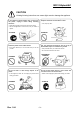
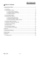
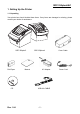
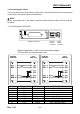
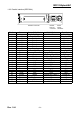
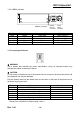
Table Of Contents
- 1. Setting Up the Printer
- 1-1 Unpacking
- 1-2 Connecting the Cables
- 1-3 Connecting the Drawer
- 1-4 Setting the Dip Switches
- 1-5 Setting the Memory Switches
- 1-6 Installing or Replacing the Paper Roll
- 1-7 Adjustments and Settings
- 1-8 Using the Printer
- 1-9 Connecting the computer
- 1-10 Connecting the Power Supply
- 2. Self test
- 3. Hexadecimal Dumping
- 4. Specification
- 5. Appendix

Rev. 1.04
- 10 -
SRP-350plusA&C
1-2-3 USB2.0 Interface
Pin No. Signal Name Assignment (Color) Function
Shell Shield Drain Wire Frame Ground
1 VBUS Red Host Power
2 D- White Data Line(D-)
3 D+ Green Data Line(D+)
4 GND Black Signal Ground
1-3 Connecting the Drawer
※ WARNING
Use a drawer that matches the printer specification. Using an improper drawer may
damage the drawer as well as the printer.
※ CAUTION
Do not connect a telephone line to the drawer kick-out connector; otherwise the printer and
the telephone line may be damaged.
Plug the drawer cable into the drawer kick-out connector on the back of the printer next to
the power supply connector.
Pin No. Signal name Direction
1 Frame ground -
2 Drawer kick- out drive signal 1 Output
3 Drawer open/close signal Input
4 +24V -
5 Drawer kick- out drive signal 2 Output
6 Signal ground -
※ Drawer Port is 24Vdc/2.5A Output rating, Class 1.
Drawer
kick-out
connector
Power
supply
connector
USB2.0 connector