
User`s manual


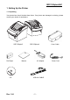
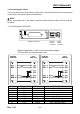
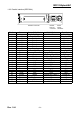
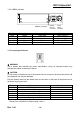
Table Of Contents
- 1. Setting Up the Printer
- 1-1 Unpacking
- 1-2 Connecting the Cables
- 1-3 Connecting the Drawer
- 1-4 Setting the Dip Switches
- 1-5 Setting the Memory Switches
- 1-6 Installing or Replacing the Paper Roll
- 1-7 Adjustments and Settings
- 1-8 Using the Printer
- 1-9 Connecting the computer
- 1-10 Connecting the Power Supply
- 2. Self test
- 3. Hexadecimal Dumping
- 4. Specification
- 5. Appendix

Rev. 1.04
- 8 -
SRP-350plusA&C
1-2 Connecting the Cables
You can connect up the three cables to the printer. They all connect to the connector panel
on the back of the printer, which is shown below:
※ NOTE
Before connecting any of the cables, make sure that both the printer and the host are
turned off.
1-2-1 Serial Interface (RS-232C)
※ When the Dip Switch is “ON” on the Serial Interface Board,
DTR and RTS are connected each other.
Pin No. Signal name Direction Function
1 FG - Frame Ground
2 TxD Output Transmit Data
3 RxD Input Receive Data
4 RTS Output Ready To Send
5 CTS Input Clear To Send
6 DSR Input Data Set Ready
7 SG - Signal Ground
20 DTR Output Data Terminal Ready
Drawer
kick-out
connector
Power
supply
connector
Interface connector
PRINTER
SIDE (25P)
HOST
SIDE (25P)
PRINTER
SIDE (25P)
HOST
SIDE (9P)