Service Manual SRP-F310/312 Front Exit Thermal Printer Rev. 1.00 http://www.bixolon.
SRP-F310/312 ■ Table of Contents 1. Precaution Segment ...................................................................................................................................4 1-1 Safety Precautions..................................................................................................................................4 1-2 Servicing Precaution...............................................................................................................................
SRP-F310/312 4. Hardware ...................................................................................................................................................33 4-1 Wiring Diagram .....................................................................................................................................33 4-2 Block Diagram.......................................................................................................................................
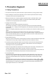
SRP-F310/312 1. Precaution Segment 1-1 Safety Precautions 1. Be sure that all of the built-in protective devices are replaced. Restore any missing protective shields. 2. When reinstalling the chassis and its assemblies, be sure to restore all protective devices including: nonmetallic control knobs and compartment covers. 3. Make sure that there are no cabinet openings through which people – particularly children - might insert fingers and contact dangerous voltages.
SRP-F310/312 1-2 Servicing Precaution WARNING 1: First read the Safety Precaution section of this manual. If some unforeseen circumstance creates a conflict between the servicing and safety precautions, always follow the safety precaution. WARNING 2: An electrolytic capacitor installed with the wrong polarity might explode. 1.
SRP-F310/312 1-3 Precaution for Electrostatically Sensitive Devices (ESDs) 1. Some semiconductor (solid state) devices are easily damaged by static electricity. Such components are called Electrostatically Sensitive Devices (ESDs); examples include integrated circuits and some field-effect transistors. The following techniques will reduce the occurrence of component damaged caused by static electricity. 2.
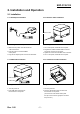
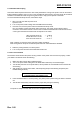
SRP-F310/312 2. Installation and Operation 2-1 Installation 2-1-2 Interface Cable Installation 2-1-1 AC Adapter Installation Interface Cable Interface connector Figure 2-2 I/F Cable Installation Figure 2-1 AC Adapter Installation 1. Make sure the printer is turned off with the side of the switch. 2. Plug the power cord into the SMPS on the printer. 3. Plug the AC Adapter power cord into the wall outlet. 1. Turn off the printer, host ECR and Computer. 2.
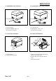
SRP-F310/312 2-1-5 ETHERNET Cable Installation 2-1-6 Dongle(Usb A-Type) Cable Installation Interface Connector Dongle Cable Figure 2-5 ETHERNET Cable Installation Figure 2-6 Dongle Cable Installation 1. Turn the printer off.. 2. Plug the ETHERNET Cable into the connector on the printer. 1. Turn the printer off.. 2. Plug the Dongle Cable into the connector on the printer.
SRP-F310/312 2-2 Operation 2-2-1 Setting the DIP switches The DIP switches are located on the bottom of the printer. The DIP switches are used to set the printer to perform various functions. Follow these when changing DIP switches setting: 1. 2. 3. Turn the printer power switch off. Open the Cover . Flip the DIP switches using tweezers or another marrow-ended tool. Switches are in when up and off when off down in the Figure 2-9. The new setting takes effect when you turn on the printer.
SRP-F310/312 2-2-4 Hexadecimal Dumping This feature allows experienced users to see exactly what data is coming to the printer. This can be useful in finding software problems. when you turn on the hexadecimal dump function, the printer prints all commands and data in hexadecimal format along with a guide section to help you find specific commands. To use the hexadecimal dump function, follow these steps: 1. After you make sure that the printer is off. Open the cover. 2.
SRP-F310/312 ASCII !"#$%&'()*+,-./0123456789:;<=>?@ "#$%&'()*+,-./0123456789:;<=>?@A #$%&'()*+,-./0123456789:;<=>?@AB $%&'()*+,-./0123456789:;<=>?@ABC %&'()*+,-./0123456789:;<=>?@ABCD &'()*+,-./0123456789:;<=>?@ABCDE '()*+,-./0123456789:;<=>?@ABCDEF ()*+,-./0123456789:;<=>?@ABCDEFG ) * + , - . / 0 1 2 3 4 5 67 8 9 : ; < = > ? @ A B C D E F G H *+,-./0123456789:;<=>?@ABCDEFGHI +,-./0123456789:;<=>?@ABCDEFGHIJ , -. /0 1 2 3 4 5 6 7 8 9 : ; < = > ? @ A B C D E F G H I J K -./0123456789:;<=>?@ABCDEFGHIJKL .
SRP-F310/312 2-2-6 Setting the Memory Switches This printer has Memory Switch set which is software switches. Memory Switch set has MSW1, MSW2,MSW3, MSW4, MSW5, MSW6, MSW11, MSW12, Customize value. Memory Switch setting utility can change the Memory Switch set to ON or OFF as shown in the table below (default: all OFF): Settings of the Memory Switch are stored in the NV memory: therefore, even if the printer is turned off, the settings are maintained.
SRP-F310/312 MSW2-3~MSW2-8 MSW2-8 MSW2-7 OFF OFF OFF OFF OFF OFF OFF OFF OFF OFF OFF OFF OFF OFF OFF OFF OFF ON OFF ON OFF ON OFF ON OFF ON OFF ON OFF ON OFF ON ON OFF ON OFF ON OFF ON OFF ON OFF ON OFF ON OFF ON OFF ON ON ON ON ON ON ON ON ON ON ON ON ON ON ON ON OFF OFF MSW3 Switch MSW 3-1 MSW 3-2 MSW 3-3 1~8 Rev. 1.
SRP-F310/312 MSW\4-3~MSW4-4 MSW 3-4 OFF OFF ON MSW 3-3 OFF ON OFF MSW\4-5~MSW4-7 MSW 4-7 MSW 4-6 OFF OFF OFF OFF OFF ON OFF ON ON OFF MSW5 Switch MSW 5-1 MSW 5-2 MSW 5-3 MSW 5-4 MSW 5-5 MSW 5-6 MSW 5-7 MSW 5-8 MSW6 Switch MSW 6-1 MSW 6-2 MSW 6-3 MSW 6-4 MSW 6-5 MSW 6-6 MSW 6-7 MSW 6-8 Single byte Font Selection Font A Font B Font C MSW 4-5 OFF ON OFF ON OFF Double byte font type KS5601 SHIFT-JIS BIG5 GB2312 GB18030 Remark 12x24 9x17 9x24 Remark Function ON OFF Auto cutter function Reserved 2 color
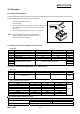
SRP-F310/312 3. Product Specifications 3-1 Appearance 3-1-1 Printer Dimensions (mm) SRP-F310/312 Figure 3-1 Printer Dimension 3-1-2 AC Adapter Dimensions (mm) 150mm 31mm 120mm 56mm Figure 3-2 Adapter Dimension Rev. 1.
SRP-F310/312 3-1-3 Feature Locations-SRP-F310/312 1. 2. 3. 4. 5. 6. 7. 8. 9. 10. Paper Sensor Control 11. Auto-Cutter 12A. Parallel interface(IEEE-1284) 12B. Serial interface(RS-232C) 12C. Default interface 13. USB B-TYPE 2.0 14. ETHERNET 15. Dongle 16. ETHERNET, WLAN Reset 17. DK(RJ11) cover-open case-lower function-led feed-button Push Button Power Button cover Dip Switch SMPS TPH Figure 3-3 Feature Location Rev. 1.
SRP-F310/312 3-2 General Specifications Item Product Processor Memory Interface Serial (RS-232C) Interface Parallel USB USB2.
SRP-F310/312 3-3 Thermal Printer Specifications 3-3-1 Printer Specification 1) 180dpi Item Description Model • SRP-F310 (TPH: KRB-72-7TA02-BIX2,KYOCERA CORPORATION) Print Method • Thermal Line Printing Dot Density • 0.141 mm(7 Dots/mm) Printing Direction • Unidirection with friction feed Printing Width • 72.2mm, 512 dot Position Character / Line • 42 (Font A: 12x24) Character Spacing • 0.28mm (0.01) (2 dots) (Font A) • 0.28mm (0.01) (2 dots) (Font B) Printing Speed • Mono Max. 270mm (63.
SRP-F310/312 3-3-3 Paper Specification Item Description Paper Type • Mono:TF50KS-E(Nippon paper) • 2Color: PB-70(Mitsubishi) Paper Form • Paper Roll Paper Width • 80mm / 83mm Paper Roll Size • Max 105mm(3.26”) Spool Inside Dia. • 12mm (0.47) Spool Outside Dia. • 18mm (0.71) Remark Table 3-5 Thermal Printer Paper Specification ※ Note * Mono: The Following paper can be used instead of the specified paper above. TF50KS-E(Paper thickness: 65μm): Nippon Paper industries Co., Ltd.
SRP-F310/312 3-3-5 Printable Area a b d c e Figure 3-4 Printable Area 1) 180dpi Item Description a 80±0.5mm(3.15 ±0.0197) b 0.141 (0.0056 ) c 72.2±0.2mm(2.83 ±0.0079) d 2.75mm~4.25mm e 2.75mm~4.25mm Dots 512 Font 9X17 56 Character Font 12X24 42 Character * ‘d’ & ‘e’ position can be shifted while printing according to the paper position. Remark 2) 203dpi Item Description A 80±0.5mm(3.15 ±0.0197) B 0.125 (0.0049 ) C 80mm±0.2mm (2.83±0.0079) D 2.75mm~4.25mm E 2.75mm~4.
SRP-F310/312 Item Maximum Unit Print Cycle (S.L.T.) 0.46 ms/Line Supply Energy 0.20 mJ/Dot Supply Voltage 24 Substrate Temperature 70 V ℃ Number of heating dots at same time 256 Dots Logic Supply Voltage (VDD) 3.
SRP-F310/312 3-4 SMPS Specifications 3-4-1 SMPS (Switching Mode Power Supply) Specification Item Description • Typical: 100V ~ 240V AC • Min: 90V AC • Max: 264V ac • Max: 1.5A (When 120V) • Max: 30A at 115Vac input Voltage for a cold start at 25℃ ambient conditions • +24V ±5% @ 0~2.5A Static • +24V +5/-10% @ 2~6.5A Dynamic • ±200mV @ 24Vdc • The power supply shall not be damaged from the condition that between DC output and DC ground are shorted.
SRP-F310/312 3-5 Interface Specifications 3-5-1 RS-232C Serial Interface 3-5-1(a) Specification Item Data Transmission Synchronization HandShaking (Flow Control) Signal Level Baud Rate Data Word Length Parity Connector Description • Serial • Asynchronous • H/W: DTR/DSR • S/W: XON/XOFF • Logic1 (MARK): -3V ~ -15V • Logic0 (SPACE): +3V ~ +15V • 2400/4800/9600/19200/38400/57600/115200 bps • 8 bits • None • DB25P Female (I/F PBA) Table 3-14 RS-232C Specification Remark XON: ASC Code 11h XOFF:ASC Code 13h ※
SRP-F310/312 3-5-1(c) Cable Connection PRINTER SIDE (25P) HOST SIDE (25P) PRINTER SIDE (25P) HOST SIDE (9P) Figure 3-7 RS-232C Cable Connection 3-5-1(d) Signal Description Pin No. 1 2 3 4 5 Signal name FG TxD RxD RTS CTS 6 DSR 7 SG 20 DTR Rev. 1.00 Direction Output Input Output Input Function Frame Ground Transmit Data Receive Data Ready To Send Clear To Send This signal indicates whether the host computer can receive data. (H/W flow control) 1) MARK(Logic1): The host can receive a data.
SRP-F310/312 3-5-1(e) H/W Flow Control When DTR/DSR flow control is select, before transmitting a data, the Printer checks whether the host is BUSY or not. If the host is BUSY, the Printer does not transmit a data to the host. If the host is not BUSY, the Printer transmits a data to the Host. The host is the same. Refer to the Interface Part of Chapter 7 (Special Circuit Diagrams).
SRP-F310/312 3-5-2(c) Signal Specification (Compatibility/Nibble/Byte mode) Pin No.
SRP-F310/312 3-5-3 USB2.0 Interface SRP-F310/312 support the USB (Universal Serial Bus) Serial Communication. 3-5-3(a) Specification Item Transfer Type Data Signal Data Format Speed Cable & Connector Other Description • BULK • Bi-direction, Half-Duplex • Differential Signal Pair (D+ / D-) • NRZI Format • Zero Bit Stuffing after 6 ones • 480 Mbps • Cable: 5m / 2m • Connector: B Type(Device) / A Type(Host) • Supports the 480 Mbps high-speed mode (HS) for USB 2.
SRP-F310/312 Figure 3-9 USB Cable 3-5-4(d) Construction Raw materials used in the fabrication of this cable must be of such quality that the fabricated cable is capable of meeting or exceeding the mechanical and electrical performance criteria of the most current USB Specification revision and all applicable domestic and international safety/testing agency requirements; e.g., UL, CSA, BSA, NEC, etc., for electronic signaling and power distribution cables in its category.
SRP-F310/312 ※ Note: Minimum conductor construction must be stranded tinned copper. To minimize end user termination problems, USB uses a keyed connector protocol. The physical difference in the Series A and B connectors insures proper end user connectivity. The A connector is the principle means of connecting USB devices directly to a host or to the downstream port of a hub. All USB devices must have the standard Series A connector specified in this chapter.
SRP-F310/312 3-6 Cash Drawer Specifications 3-6-1 Drawer Cable Ferrite Core: 1 turn (OP-18E: 18.2 x 12.5 x 25.5) Figure 3-11 Drawer Cable 3-6-2 Cable Connection Pin No. 1 2 3 4 5 6 Description Frame GND Drawer Kick-Out Driver Signal #1 Drawer Open / Close Signal +24V Drawer Kick-Out Driver Signal #2 Signal GND Table 3-21 Drawer Cable Connection ※ Note: +24V is always output through pin 4 during power on. Rev. 1.
SRP-F310/312 3-7 ETHERNET Specifications 3-7-1 Ethernet 1) Ethernet specifications Network Interface: 10/100 Base-T All in one type (Auto detection) [Protocol] Layer Network Layers Transport Layers Application Layers Protocol ARP, IP, ICMP TCP, UDP DHCP, DNS, Raw Print, SMTP(notify Printer status) HTTP, HTTPS(setting), FTP (settings), TELNET (settings) 2) Ethernet cable 3) Ethernet signal descriptions Pin No.
SRP-F310/312 3-7-2 WLAN 1) WLAN specifications Support IEEE 802.11b/g Infrastructure, Ad-hoc mode. Frequency Band and Operating Channels] Item Description Frequency band 2.4000 – 2.497 GHz Modulation OFDM with BPSK, QPSK, 16QAM, 64QAM (11g) BPSK, QPSK, CCK (11b) Data rate : 54/48/36/24/18/12/11/9/6/5.
SRP-F310/312 4. Hardware 4-1 Wiring Diagram [Figure 4-1 Board Wiring Diagram] Rev. 1.
SRP-F310/312 4-2 Block Diagram Rev. 1.
SRP-F310/312 Rev. 1.
SRP-F310/312 Rev. 1.
SRP-F310/312 Rev. 1.
SRP-F310/312 [Figure 4-2 Block Diagram] Rev. 1.
SRP-F310/312 4-3 Special Circuit Descriptions 4-3-1 Power Circuit This system is operated under 100Vac or 240Vac. The power circuit supplies the three differential DC voltage sources. [Figure 4-3 Power Block Diagram] 1) Drawer Driving and Feed, Auto Cutter Motor Voltage and TPH Driving Voltage: +24VDC +24VDC is supplied from SMPS. This Voltage is smoothed by capacitors (CE1).
SRP-F310/312 6) FPGA core Voltage: +1.5VDC Step down voltage the input +2.5VDC to +1.5VDC by a regulation.U16(BH15PB1WHFV-TR) 7) CPU core Voltage: +1.2VDC Step down voltage the input +24VDC to +1.2VDC by a switching regulation.U13(A4490SES-T) 4-3-2 RESET Circuit Reset signal is signal in order to start-up CPU under Power-on. Reset circuit uses a reset ASM811REUSF-T(U8). When 3.3Vdc is fallen under 2.7Vdc by Power-off, reset signal prohibits the system from miss-operating by lowering down to 0V.
SRP-F310/312 4-3-3 Buzzer and Cash Drawer Circuits 1) Buzzer Driving Circuit The Buzzer is used to inform several kinds of states which occur under system operating and gives some information to users by controlling the CPU (SPEAr300) [Figure 4-6 Buzzer Block Diagram] 2) Cash Drawer Driving Circuit The circuit is used for opening cash drawer and driven by the Q301, Q302(2SD2170). When its state is high level signal, Q301 or Q302 (2SD2170) drive the solenoid to open the cash drawer.
SRP-F310/312 4-3-4 I/F PBA Detect Block Diagram When the printer is ON, the printer checks what kind of the I/F PBA is installed. After detection, the CPU specify the I/O port properly. The following is the method of I/F PBA detection. The I/F PBA has the three return Signal (MD0~2). The CPU recognize the I/F PBA by the value of the three return signal. I/F PBA RS-232C IEEE1284 No Connection MD0 L H L MD1 H L L MD2 L L L 4-3-5 RS-232C Communication Block Diagram The CPU is used for serial communication.
SRP-F310/312 4-3-6 Parallel Communication Block Diagram The printer support the bidirectional Parallel Interface with Centronics, Nibble, Byte Mode. The Centronics is Forward and the Nibble, Byte are reverse Mode. [Figure 4-10 IEEE1284 Communication Block Diagram] 4-3-7 USB Communication Block Diagram The printer support the USB (Universal Serial Bus). The transfer type of the printer is the BULK. [Figure 4-11 USB2.
SRP-F310/312 4-3-9 Thermal Printer Head Circuit First, the CPU sends a Serial Clock and Serial Data 256bits(32Bytes) to the Shift Register of the Thermal Printer. The Serial Data are stored to each Shift Register in the Thermal Printer. Because the Data#1 Pin and the Data#2 pin are shorted on Main PCB, the Data(256bits) are stored in both Shift Register#1 and #2. Second, the CPU send a Latch Signal to the Thermal Printer.
SRP-F310/312 5. Disassembly and Assembly 5-1 Case lower block 1. Remove the ①two screws. 2. Separate the ②COVER DOWN-FRONT 1. Remove the ①two screws. 2. Separate the ②INTERFACE DEFAULT Rev. 1.
SRP-F310/312 1. Separate the ①COVER DIP-SWITCH form the SRP-F310/312 2. Remove the ②SMPS 1. Remove the ①two screws. 2. Separate the ②ASE LOWER Rev. 1.
SRP-F310/312 1. Separate the ①FPC from MAIN PCB 2. Separate the ②FIVE CONNECTOR from MAIN PCB 1. Remove the ①four screws. 2. Separate the ②MAIN PCB from ④BRACKET PCB. 3. Remove the ③two screw. 4. Separate the ④BRACKET PCB from SRP-F310/312. Rev. 1.
SRP-F310/312 5-2 Case Upper block 1. Remove the ①screw 2. Separate the ②LOCK SPRING, ③SPRING HINGE 3. Remove the ⑥E-Ring. 4. Separate the ⑤SHAFT HINGE From ④ASS`Y CASE-UPPER 1. Remove ①two screws. 2. Separate the ②ASS`Y TPH From ASS`Y CASE-UPPER Rev. 1.
SRP-F310/312 1. Remove the ①two screws. 2. Separate the ②CASE UPPER from the ASSY HOUSING. 3. Separate the ③COVER UP-FRONT from ②CASE UPPER 4. Remove the ④screw. 5. Separate the ⑤COVER HINGE from the ASSY HOUSING. 1. Remove the ①four screws. 2. Separate the ②BRACKET HOUSING from the ASSY HOUSING 3. Separate the ⑥two WASHER from the ⑤SHAFT HINGE 4. Separate the ⑤SHAFT HINGE and ③BRACKET HOOK and ④SPRING from the ②BRACKET HOUSING 5. Remove the ⑧screw. 6. Separate the ⑨PCB LED from the ⑦COVER HOUSING 7.
SRP-F310/312 1. Remove the ①two screws. 2. Separate the ②GUIDE TPH from the ASSY TPH 3. Remove the ⑥screw. 4. Separate the ASSY FIXED CUTTER from the ASSY TPH 5. Remove the ③two screws. Rev. 1.00 6. Separate the ④CUTTER from the ⑤GUIDE CUTTER 7. Remove the ⑫SPECIAL SCREW. 8. Separate the ⑪E-RING, ⑩SHAFT TPH from the ⑦TPH 9.
SRP-F310/312 5-3 Frame block 1. Remove the ①two screws. 2. Separate the ASSY CUTTER from the FRAME MAIN 3. Remove the ③four screws. 4. Separate the ④AUTO CUTTER from the ②BRACKET CUTTER 1. Separate the ①PARTITION from the FRAME MAIN 2. Remover the ③WASHER. 3. Separate the ②SHAFT FEED from the FRAME MAIN 4. Remover the ④WASHER. 5. Separate the ⑤PUSH BUTTON And ⑥SPRING LOCK-L from the FRAME MAIN Rev. 1.
SRP-F310/312 1. Remove the ①four screws. 2. Separate the ②BRACKET MAIN From the FRAME MAIN 3. Remove the ③screw. 4. Separate the ④COVER OPEN S/W From the FRAME MAIN 5. Remove the ⑤screw. 6. Separate the ⑥PCB FEED From the FRAME MAIN 7. Remove the ⑦screw. 8. Separate the ⑧PCB PAPER-END From the FRAME MAIN 1. Remove the ①screw, And separate the NEAR END SENSOR from from the BRACKET MAIN the BRACKET MAIN.\ 9. Remove the ⑪SCREW. 2. Remover the ⑥SCREW. 10. Separate the ⑫ PCB-DK 3.
SRP-F310/312 6. Adjustments and Maintenance 6-1 Adjustment 6-1-1 Remaining Roll Paper Adjustment This sensor is set to the step4 position at the factory. If you find that there is not or too enough paper remaining on the roll when the near-end sensor is triggered, you can change the setting to the upper or Lower position as described below. Note: The factory setting is based on a paper roll core with an outside diameter of 18mm.
SRP-F310/312 6-2 Maintenance Paper dust in the heating elements may lower the print quality. In this case, clean the print head as follow; ※ Caution: Turn off the printer power before cleaning. ※ Caution: Note that the thermal head (Thermal element and Radiation plate) becomes very hot during normal operation, creating the danger of burn injury. Be sure to wait for about 10 minutes after turning printer power off before beginning the cleaning. 1. Open the cover-open. 2.
SRP-F310/312 7. Troubleshooting This chapter describes the methods for troubleshooting in this Receipt Printer. 7-1 Troubleshooting flow chart If the source of a problem is not clear, use the flowchart below to find and replace a defective component. Normally, servicing should be performed by component replacement. Repairs of the PCBs and other components should be performed only by technicians. Rev. 1.
SRP-F310/312 7-1-1 POWER LED does not light A Is AC adaptor & power cord connected properly? NO Connect AC adaptor & power cord properly. YES OK? NO YES END Does AC adaptor have proper output voltage rating? (approx. +24V) NO Replace AC adaptor. OK? NO YES YES END Has fuse F1 on main PCB blown? YES Replace fuse F1 OK? NO NO YES END Is POWER LED continuity normal? NO Replace Operation panel ass’y YES OK? NO YES Replace PCB-main ass’y END END Rev. 1.
SRP-F310/312 7-1-2 Paper and Error led blink Rev. 1.
SRP-F310/312 7-1-3 Paper and Error led lit C Turn power off, then once again OK? YES END NO Is paper roll not inserted? NO Replace or insert paper roll YES OK? NO YES END Is paper-end sensor, continuity normal? NO Replace Sensor-paper-end ass’y YES NO OK? YES END Replace PCB-main ass’y END Rev. 1.
SRP-F310/312 7-1-4 Paper led lit D Turn power off, then once again OK? YES END NO Is paper roll in paper near-end condition? NO Replace or insert paper roll YES OK? NO YES END Is paper near-end sensor continuity normal? NO Replace Sensor-paper-near end ass’y YES OK? NO YES END Replace PCB-main ass’y END Rev. 1.
SRP-F310/312 7-1-5 Error led blink E Turn power off, then once again OK? YES END NO Is correct I/F PBA inserted? NO Replace I/F PBA NO OK? YES YES END Replace PCB-main ass’y END Rev. 1.
SRP-F310/312 7-1-6 Error led lit Rev. 1.
SRP-F310/312 7-1-7 Self test is not normal G *1 VH : +24V VCC : +5V Does not printer operate at all? YES Is output voltage of regulator on PCB-main within SPEC?(*1) NO Replace PCB-main ass’y Printing is carried out, but print quality is deficient or paper feeding is not normal YES Replace printer mechanism ass’y Replace printer mechanism ass’y NO YES END Replace PCB-main ass’y END Rev. 1.
SRP-F310/312 7-1-8 Data from host is not printed normally H Send data from host to printer OK? YES END NO Are interface parameters set to identical values at host and printer? NO Make settings identical OK? NO YES YES END Does interface cable match specifications? NO Replace with a proper cable YES NO OK? Replace interface PCB ass’y YES END OK? YES END NO Is the interface wire broken? YES Replace the interface cable NO OK? NO YES Replace printer mechanism ass’y END OK? YES
SRP-F310/312 7-2 Power Problem If a problem that can be verified by visual examination has occurred, use the tables below to determine the cause and perform repairs. There are four tables, divided by symptom category: • Printing Quality Problems • Printer Mechanism Problems • Auto cutter Mechanism Problems The tables contains the following columns: • Problem This is the symptom that can be verified • Problem Causes This is a listing of one or several possible causes that should be examined.
SRP-F310/312 7-2-1 Printing Quality Problems Problem Certain parts are printed with vertical white lines Certain parts are printed with vertical black lines Horizontal black lines are generated or the vertical width of the characters is reduced Overall printing density is low Rev. 1.
SRP-F310/312 7-2-2 Printer Mechanism Problems Problem Probable Cause Level Checkpoint Check for short failure inside the motor Check the assembly status of the washers holding the gears Feeding motor failure B Gear is dislocated from the rotating axis B Paper jam o B Check for paper jam Auto cutter jam B Check for auto cutter jam Auto cutter jam B Check for auto cutter jam Deformation of Hook B Check for deformation of Hook Cover Open sensor failure B Check for sensor failure Replace