USER’S MANUAL STP-103 THERMAL PRINTER PO WE R ERR OR FEE D ON LIN E KN04-00003A Rev. 2.6 www.samsungminiprinters.
Safety Precautions In using the present appliance, please keep the following safety regulations in order to prevent any hazard or material damage. WARNING Violating following instructions can cause serious injury or death. Do not plug several products in one multi-outlet. You must use only the supplied adapter. It is dangerous to use other adapters. This can provoke over-heating and a fire. If the plug is wet or dirty, dry or wipe it before usage.
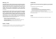
Warning – U.S Introduction This equipment has been tasted and found to comply with the limits for a Class A digital device, pursuant to Part 15 of the FCC Rules. These limits are designed to provide reasonable protection against harmful interference when the equipment is operated in a commercial environment. This equipment generates, uses, and can radiate radio frequency energy and, if not installed and uses in accordance with the instruction manual, may cause harmful interference to radio communications.
Table of Contents Chapter 1. Unpacking 1-1. Checking the contents of the Printer Chapter 1. Unpacking ...........................................................7 1-1. Checking the contents of the Printer ........................................................7 1-2. Locating the Printer ..................................................................................7 1-3. Printer Part names ...................................................................................8 1-4.
1-3. Printer Part Names 1-4. Operating Control Panel The control panel has two buttons and two lights. (1) Cover top (2) Case top (3) Case bottom (4) Control panel (5) Roller (6) Power switch (7) Interface connector (male) (8) DC Jack (9) Interface connector (female) (10) Roll paper (11) Detector switch (10) (5) (1) POWER ERROR FEED ON LINE Rear View (11) Buttons The control panel buttons perform paper feeding and on line function.
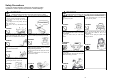
Chapter 2. Connecting the Cable 2-1. Connecting the AC adapter to your printer When the printer is used, use the optional AC adapter, NH36-240150-I1 for your printer. WARNING Using an incorrect power supply may cause fire or electrical. 2-2. Connecting the printer to your Computer STP-103S You need an appropriate serial interface cable to connect your computer to the printer's built-in interface. 1.
2-2. Connecting the printer to your Computer STP-103P Chapter 3. Installing the Paper Roll Use a paper roll that matches the specifications. You need an appropriate parallel interface cable to connect your computer to the printer's built-in interface. 1. Make sure that both the printer and computer are turned off : then plug the cable connector securely into the printer's interface connector. 2. Tighten the screws on both sides of the cable connector.
Chapter 4. Setting the DIP Switches CAUTION Turn off the printer while setting the DIP switch to prevent an electrical short, which can damage the printer. You can change your interface and printer density settings by changing the DIP switch setting. 1. Make sure the printer is turned off. 2. There are a switch. Notice that ON is marked on each set of switches. Use tweezers or another narrow tool to move the switches.
Chapter 5. Running the Self-test Chapter 6. Hexadecimal Dumping 1. Self-test printing This feature allows experienced users to see exactly what data is coming to the printer. This can be useful in finding software problems. When you turn on the hexadecimal dump function, the printer prints all commands and data in hexadecimal format along with a guide section to help you find specific commands.
Chapter 7. Code Table The following pages show the character code tables. To find the character corresponding to a hexadecimal number, count across the top of the table for the For example, 4A=J.
PC850 : Multilingual 20 PC860 : Portuguese 21
PC863 : Canadian – French 22 PC865 : Nordic 23
SP PC858: Euro 24 Space Page 25
Chapter 8. Functions The commands listed in the table below are available for control of the printer.
Chapter 9.
CR [Name] [Format] Print and carriage return. ASCII HT Hex 0D Decimal 13 [Description] When automatic line feed is enabled, this command functions the same as LF; when automatic line feed is disabled, this command is ignored. DLE EOT n [Name] [Format] Real-time status transmission. ASCII DLE EOT n HEX 10 04 n Decimal 16 4 n [Range] 1≤n≤4 [Description] Transmits the selected printer status specified by n in real time, according to the following parameters: n=1 : Transmit printer status.
ESC ! n [Name] [Format] Select print mode(s) ASCII ESC ! n Hex 1B 21 n Decimal 27 33 n [Range] 0 ≤ n ≤ 255 [Description] Selects print mode(s) using n as following table in next page. Bit 0 1 2 3 4 5 6 7 Off/On Off On Off On Off On Off On Off On Off On Hex 00 01 00 02 00 08 00 10 00 20 00 80 Decimal 0 1 0 2 0 8 0 16 0 32 0 128 Function 24 character (font A : 12 ×24) 42 character (font B : 9 ×24) Undefined 32 character (font A : 12 ×24) Undefined Emphasized mode not selected. Emphasized mode selected.
ESC 2 [Name] [Format] ESC @ [Name] [Format] Select 1/6-inch line spacing ASCII ESC 2 Hex 1B 32 Decimal 27 50 [Description] Selects 1/6-inch line spacing. Initialize printer ASCII ESC @ Hex 1B 40 Decimal 27 64 [Description] Clears the data in the print buffer and resets the printer mode to the mode that was in effect when the power was turned on.
ESC R n [Name] [Format] Select an international character set ASCII ESC R n Hex 1B 52 n Decimal 27 82 n [Range] 0 ≤n ≤10 [Description] Selects an international character set n from the following table: n 0 1 2 3 4 5 6 7 8 9 10 Character set U.S.A. France Germany U.K Denmark Ⅰ Sweden Italy Spain Japan Norway Denmark Ⅱ ESC V n [Name] [Format] Turn 90° clockwise rotation mode on/off ASCII ESC V n Hex 1B 56 n Decimal 27 86 n [Range] 0 ≤n ≤1, 48 ≤n ≤49 [Description] Turns 90° clockwise rotation mode on off.
ESC c 5 n [Name] [Format] ESC { n [Name] [Format] ESC d n [Name] [Format] FS p n m [Name] [Format] Enable/disable panel FEED buttons ASCII ESC c 5 n Hex 1B 63 35 n Decimal 27 99 53 n [Range] 0 ≤n ≤255 [Description] Enables or disables the panel buttons. ● When the LSB of n is 0, the panel FEED buttons are enabled. ● When the LSB of n is 1, the panel FEED buttons are disabled.
GS ! n [Name] [Format] Select character size ASCII GS ! n Hex 1D 21 n Decimal 29 33 n [Range] 0 ≤n ≤255 Where 1 ≤ Number of times of character height ≤2 1 ≤ Number of times of character width ≤2 [Description] Selects the character height using bits 0 to 1 and selects the character width using bits 4 to 7, as follows: Bit 0 1 2 3 4 5 6 7 Off/On Hex Decimal Function Character height selection. See Table 2.
n selects the printing position as follows: N 0,48 1,49 2,50 3,51 [Default] GS P x y [Name] [Format] Set horizontal and vertical motion units ASCII GS P x y Hex 1D 50 x y Decimal 29 80 x y [Range] 0 ≤ x ≤ 255 0 ≤ y ≤ 255 [Description] Sets the horizontal and vertical motion units to 1/x inch, respectively. When x is set to 0, the default setting value is used. When y is set to 0, the default setting value is used.
● When the LSB of m = 1: After waiting for the period specified by t, the LED indicator blinks and the printer waits for the PAPER FEED button to be pressed. After the button is pressed, the printer executes the macro once, The printer repeats the operation r times.
GS f n [Name] [Format] Select font for Human Readable interpretation (HRI) characters. ASCII GS f n Hex 1D 66 n Decimal 29 102 n [Range] n = 0, 1, 48, 49 [Description] Selects a font for the HRI characters used when printing a bar code. n selects a font from the following table: n 0,48 1,49 Font Font A (12 * 24) Font B (9 * 24) GS h n [Name] [Format] Set bar code height ASCII GS h n Hex 1D 68 n Decimal 29 104 n [Range] 1 ≤n ≤255 [Description] Sets the height of the bar code.
Printing GS k 72 7 67 111 100 101 13 57 51 ② Special characters are defined by combining two characters “{“ and one character. The ASCII character “{“ is defined by transmitting “{“ twice consecutively. Specific character [When CODE128 (m=73) is used :] ● Refer to Appendix J for the information of the CODE128 bar code and its code table.
GS v 0 xL xH yL yH dl…dk [Name] Print raster bit image [Format] ASCII GS v 0 m xL xH Hex 1D 76 30 m xL xH Decimal 29 118 48 m xL xH [Range] 0 ≤ m ≤ 3 , 48 ≤ m ≤ 51 0≤ xL ≤ 255 , 0 ≤ xH ≤ 255 , 0 ≤ yL ≤ 255 0 ≤ d ≤ 255 k = (xL+xH×256) × (yL+yH×256) (k=0) [Description] Selects raster bit-image mode.
APPENDIX B : Specification Printing method Dot density Printing width Paper width Characters per line Printing Speed Receive buffer size Supply voltage Environmental conditions MCBF ※Option : STP-103DK Thermal line printing 200 x 200 Dpi (8 dot/mm) 48mm 58mm 32 (Font A) (12x24) , 42 (Font B) (9x24) Approximately 1.97 inchs / sec 50 mm/sec at 25℃/printing duty 12.5% 15K bytes DC 24V 1.
2) Parallel Interface Connector Specification 3) Control Command PRINTER HOST 1 /STROBE (I/O) 1 /STROBE (I/O) 2 DATA0 (I/O) 2 DATA0 (I/O) 3 DATA1 (I/O) 3 DATA1 (I/O) 4 DATA2 (I/O) 4 DATA2 (I/O) 5 DATA3 (I/O) 5 DATA3 (I/O) 6 DATA4 (I/O) 6 DATA4 (I/O) 7 DATA5 (I/O) 7 DATA5 (I/O) 8 DATA6 (I/O) 8 DATA6 (I/O) 9 DATA7 (I/O) 9 DATA7 (I/O) 10 /ACK (I) 10 /ACK (I) 11 BUSY (I) 11 BUSY (I) 12 PE (I) 12 PE (I) 13 SLCT 13 SLCT 15 /ERROR (I) 15 /ERROR (I) 16 /I