Bizfon 7000 Installation Instructions (for Revision 5.
Installation Instructions Table of Contents 1 2 3 4 Installation Overview ...............................................................................................................................1 Unpacking.................................................................................................................................................2 Chassis Views .........................................................................................................................................
Installation Instructions 1 Installation Overview Installation of the Bizfon 7000 involves the following steps: 1. Unpacking 2. Mechanical Installation 3. Electrical Installation 4. Accessories Installation 5. Telephony Installation 6. Server Configuration 7. Network Installation Each of these steps will be described in the following sections. 50 Stiles Road • Salem, NH 03079 • Toll Free 1-800-260-5793 • 603-870-9400 • www.Bizfon.com © 2005 All rights reserved. Bizfon is a registered trademark.
Installation Instructions 2 Unpacking Open the box and carefully unpack it. Save all shipping and packaging materials. Verify all items against the parts list shown in Table 1. If any items are missing, contact your dealer or Bizfon Customer Support at 866255-9679 - press 3.
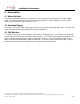
Installation Instructions 3 Chassis Views Figure 1: Front Chassis View 3 2 1 1 2 7 4 5 8 9 6 Power switch Press & Release – Normal shutdown within a few seconds Press & Hold – Forced shutdown Front panel LEDs. Power – Indicates system start up activity Drive – Indicates drive activity Alert – Indicates drive or other system fault condition 3 RJ-45 10BaseT/100BaseTX Auto-Sensing Auto-MDI/MDIX switched Local Area Network Ethernet ports.
Installation Instructions Figure 2: Rear Chassis View 11 15 13 12 14 11 Exhaust fan cover 12 Power cord connector 13 14 Voltage selection switch Permanent ground connecting screw 15 Air intake and exhaust vents 50 Stiles Road • Salem, NH 03079 • Toll Free 1-800-260-5793 • 603-870-9400 • www.Bizfon.com © 2005 All rights reserved. Bizfon is a registered trademark. All other names may be trademarks or registered trademarks of their respective owners.
Installation Instructions 4 Mechanical 4.1 Tabletop or Shelf Placement To install the Bizfon 7000 on a tabletop or shelf: 1. Remove the four rubber feet from the Accessory Kit. 2. Turn over the chassis and notice the circles on each corner. 3. Remove the paper backing from each rubber foot and place one foot in each circle. 4.2 Rack Mount To install the Bizfon 7000 in a standard 19 inch equipment rack: 1. Remove the two brackets and associated screws from the Accessory Kit. 2.
Installation Instructions Figure 4: Wall Mount Bracket Installation 4. Install the mounting brackets on each side of the chassis using four 8-32 flat head screws. 5. Secure the unit to the wall using appropriate hardware. Caution: The Bizfon server must be securely mounted to the wall to avoid equipment damage or personal injury. 50 Stiles Road • Salem, NH 03079 • Toll Free 1-800-260-5793 • 603-870-9400 • www.Bizfon.com © 2005 All rights reserved. Bizfon is a registered trademark.
Installation Instructions 5 Electrical 5.1 Chassis Ground and Voltage Selection Connect the chassis to earth ground using 18 AWG (or larger) wire from the chassis ground screw located next to the power receptacle on the rear panel as shown in Figure 5. Voltage setting switch Ground connecting screw Figure 5: Ground Connection and Voltage Selection Be sure the voltage switch on the rear of the unit is set to the appropriate setting for your location.
Installation Instructions 6 Accessories 6.1 Music-On-Hold Connect the output from your music system to the server using a 3.5mm stereo plug line-in audio adapter cable. Insert the male cable end into the audio connector labeled “In” on the front panel. Only the audio channel associated with the tip of the plug is used. 6.2 Overhead Paging Connect the server to the input of your paging system using a 3.5mm stereo plug audio cable.
Installation Instructions 7 Telephony 7.1 Analog CAUTION: To reduce the risk of fire, use only 26 AWG (or larger) UL listed or CSA certified telecommunications line cord. The server’s analog phone connections can be used to connect Central Office (CO) lines, Direct Inward Dial (DID) lines, or telephone handsets. Table 3 describes the ports. RJ-11 Ports Type 1-3 FXO (loop-start) 4-9 FXO (loop-start) or FXS 10-16 FXS Description Used to connect to Central Office (CO) lines.
Installation Instructions 8 Server Configuration The Bizfon 7000 provides an administrative interface to configure and administer the server. The administrative interface is accessed using a web browser. Assuming the network settings are set to their factory defaults, the steps to connect to this interface are: 1. Plug your PC into one of the server’s LAN ports. 2. Set up the PC’s network interface to obtain an IP address automatically (using DHCP). 3.
Installation Instructions 9 Data Network The Local Area Network (LAN) and Wide Area Network (WAN) data network ports are 10BaseT/100BaseTX auto-sensing and auto-MDI/MDIX ports. The Bizfon 7000 is a sophisticated network appliance that must be properly configured before being connected to the LAN and WAN. Note: Do not plug any network cables into the server without first properly configuring the server.
Installation Instructions 10 Configuration Example “Unlimited” number of SIP phones Bizfon 7000 Server 10/100 E-net SIP Phone 10/100 E-net SIP Phone 10/100 E-net SIP Phone Network Device 10/100 E-net E-net Switch or Hub E-net Switch or Hub Network Printer Paging Amplifier 10/100 E-net LAN WAN DSL or Cable Modem 10/100 E-net Line level audio input Line level audio output In Up to 13 outside DID lines* PSTN Central Office Out Up to 13 inside extensions* Analog Phone 10/100 E-net 10/1
Installation Instructions 11 Physical and Environmental Specifications Dimensions (W x H x D) Weight (Base Model) Power Temperature Humidity 17.5 x 15 x 3.5 inches (44.5 x 38 x 9 cm) 17 lbs AC 100-127/200-240V, 4/2A, 47-63Hz 0° ~ 40° C 15% ~ 90% RH, Non-condensing 50 Stiles Road • Salem, NH 03079 • Toll Free 1-800-260-5793 • 603-870-9400 • www.Bizfon.com © 2005 All rights reserved. Bizfon is a registered trademark. All other names may be trademarks or registered trademarks of their respective owners.
Installation Instructions 12 Regulatory Notices 12.1 FCC Part 68 This equipment complies with Part 68 of FCC rules and the requirements adopted by ACTA. On the back side of this equipment is a label that contains, among other information, a product identifier in the format US: AAAEQ##TXXXX. If requested, provide this number to the telephone company.
Installation Instructions Users should ensure for their own protection that the electrical ground connections of the power utility, telephone lines and internal metallic water pipe system, if present, are connected together. This precaution may be particularly important in rural areas. CAUTION: Users should not attempt to make such connections themselves, but should contact the appropriate electric inspection authority, or electrician, as appropriate.
Installation Instructions This digital apparatus does not exceed the Class B limits for radio noise emissions from digital apparatus set out in the Radio Interference Regulations of the Canadian Department of Communications. Le present appareil numerique n'emet pas de bruits radioelectriques depassant les limites applicables aux appareils numeriques de la class B prescrites dans le Reglement sur le brouillage radioelectrique edicte par le ministere des Communications du Canada.