INSTALLATION, OPERATION & MAINTENANCE MANUAL FARHENHEIT™ SK-F & SKX-F SERIES SHREDDER PUMPS Electric Submersible Pumps Three Phase 208V, 230V, 460V & 575V CAST IRON THREE PHASE SK08C-F SK55C-F SK15C-F SK75C-F SK22C-F SK110C-F SK37C-F SK150C-F 316 STAINLESS STEEL THREE PHASE SKX08CSS-F SKX55CSS-F SKX15CSS-F SKX75CSS-F SKX22CSS-F SKX110CSS-F SKX37CSS-F SKX150CSS-F Read this manual carefully before installing, operating or servicing these pump models. Observe all safety information.
TABLE OF CONTENTS INTRODUCTION........................................................................................................................................... 4 SAFETY ........................................................................................................................................................ 5 INSPECTION ................................................................................................................................................
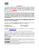
INTRODUCTION This Installation, Operation and Maintenance manual provides important information on safety and the proper inspection, disassembly, assembly and testing of the BJM Pumps® SK-F & SKX-F Series submersible pump. This manual also contains information to optimize performance and longevity of your BJM Pumps submersible pump. The F-Series fahrenheit™ pumps are engineered to pump water based liquids up to 200° Fahrenheit (93°C).
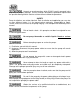
Hazards or unsafe practices which COULD result in personal injury or product or property damage. These instructions describe the procedure required and the possible damage which could result from failure to follow the procedure. SAFETY Pump installations are seldom identical. Each installation and application can vary due to many different factors. It is the owner/service mechanics responsibility to repair, service, and test to ensure that the pump integrity is not compromised according to this manual.
Pumps and related equipment must be installed and operated according to all national, local and industry standards. INSPECTION Review all safety information before servicing pump. The following are recommended installation practices/procedures for the pump. If there are questions in regards to your specific application, contact your local BJM Pumps distributor or BJM Pumps, LLC. PRE-INSTALLATION INSPECTION 1) 2) 3) 4) 5) 6) Check the pump for damage that may have occurred during shipment.
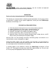
Lubrication: No additional lubrication is necessary. The shaft seal and bearings are fully lubricated from the factory. Seal oil should be checked once per year. See table: Oil Fill Quantity / Type. OIL FILL QUANTITY/TYPE OIL IN SEAL CHAMBER MODEL SK08C-F SK15C-F SK22C-F SK37C-F SK55C-F SK75C-F SK110C-F SK150C-F U.S. FL. OZ. 7.8 7.8 11.8 11.8 84.5 84.5 87.9 87.9 CC.
Risk of electric shock. Pump models; All three phase pumps do not come with electric plug connectors. To reduce the risk of electric shock, be certain that it is connected only to a properly grounded, grounding-type receptacle. Lifting: Attach a rope or lifting chain (not included) to the handle (or lifting rings) on the top of the pump. Do not lift the pump by the power cable or discharge hose/piping. Proper lifting equipment (rope/chain) must be used.
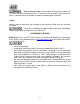
PUMP ROTATION Two ways to check the correct pump rotation: 1. By looking at the impeller; the rotation of the impeller should be counter clockwise as shown in the picture below. 2. By looking from the top of the pump. Since the impeller cannot be seen, the best way to check the rotation is to check the kick back motion of the pump when the pump just starts. The kick back motion of the pump should be counter clockwise as shown in the picture below.
PUMP OPERATION This pump is designed to handle dirty water that contains some solids. It is not designed to pump volatile or flammable liquids. Do not attempt to pump any liquids which may damage the pump or endanger personnel as a result of pump failure. Do not operate this pump where explosive vapors or flammable material exist. Death or Serious injury will result. TYPICAL MANUAL WASTEWATERING INSTALLATION NOTE: Maximum recommended starts should not exceed 10 times per hour.
STOPPING To stop the pump (manual and automatic mode), unplug it from the power source, turn off the breaker, or turn the power source off (generator). Typical 3 phase manual control 1 TYPICAL AUTOMATIC WASTEWATERING INSTALLATION NOTE: Maximum recommended starts should not exceed 10 times per hour.
Three phase pumps need a separate control box with float(s) for automatic operation. STOPPING To stop the pump (manual and automatic mode), turn off the breaker, or turn the power source off (generator). INTENDED METHODS OF CONNECTION Use with approved motor control that matches motor input in full load amperes. “UTILLISER UN DÉMARREAR APPROUVÉ CONVENANT AU COURANT Á PLEINE CHARGE DU MOTEUR.” BJM Pumps has been evaluated for use with water or water based solutions.
THREE PHASE WIRING INSTRUCTIONS FOR YOUR PROTECTION, ALWAYS DISCONNECT PUMP FROM ITS POWER SOURCE BEFORE HANDLING. “Risk of electrical shock” Do not remove power supply cord and strain relief or connect conduit directly to the pump. Installation and checking of electrical circuits and hardware should be performed by a qualified licensed electrician. To automatically operate a non-automatic three phase pump, a control panel is required. Follow the instructions provided with the panel to wire the system.
DO NOT PLACE HANDS IN PUMP SUCTION WHILE CHECKING MOTOR ROTATION. TO DO SO WILL CAUSE SERVER PERSONAL INJURY. Three phase pumps have integral motor overload protection. It is recommended that all three phase pumps using a motor starting device also incorporate motor overload protection. Pumps must be installed in accordance with the National Electrical Code and all applicable local codes and ordinances.
SERVICING YOUR SUBMERSIBLE PUMP Pump should be disconnected from the electric power supply before proceeding to do any service or maintenance. To service or repair your pump, please contact your local BJM Pumps distributor. Service should only be performed by a qualified electrician. The design of the “F” series high temperature pump models is unique and requires specific knowledge to perform the proper assembly.
7) Remove the impeller. 8) Remove the inspection screw for the oil chamber (pos#50-08). Pour out a small sample of the oil. If it is milky white, or contains water, then the oil and possible, the mechanical seal, should be changed. If an oil change is needed. 9) Remove the screws that hold the oil chamber cover in place & remove the oil. 10) Replace the mechanical seal if necessary. 11) Replace the oil. 12) Assemble the pump.
EXPLODED VIEW OF SK08C-F, SK15C-F 17
EXPLODED VIEW OF SKX08CSS-F, SKX15CSS-F 18
EXPLODED VIEW OF SK22C-F, SK37C-F 19
EXPLODED VIEW OF SKX22CSS-F, SKX37CSS-F 20
EXPLODED VIEW OF SK55C-F, SKX55CSS-F, SK75C-F, SKX75CSS-F 21
EXPLODED VIEW OF SK110C-F, SKX110CSS-F, SK150C-F, SKX150CSS-F 22
SK-F SERIES PARTS LIST Pos. No.
31D 31E 32 33 34 34 35 38 38 38E 38E-1 38F 38F 38F 38F 38F-1 50-01-2 50-02 50-07 50-08 50-11 50-11-1 50-11V 50-12 50-12-1 50-13-2 50-14-2 50-27 50-27-2 50-31E 50-32/50-33 50-32-1 50-34 50-38E 50-38F Seal Minder Sensor w/ wire Ground Wire w/Ring Term. Power Cord Line Clip / Strain Relief Seal Minder Sensor Cord Line Clip Handle / Chain Handle Bolt - Suction Cover Rod Bolts Discharge Nippple 2" Discharge Nipple 3" Discharge Elbow Gasket, Disch.
SKX-F SERIES PARTS LIST Pos. No.
33 34 34 35 38 38 38E 38E-1 38E-1 38F 38F 38F 38F 38F-1 38F-1 38F-1 38F-1 38F-1 50-01-2 50-02 50-07 50-08 50-11 50-11-1 50-11V 50-12 50-12-1 50-13-2 50-14-2 50-27 50-27-2 50-31E 50-32/50-33 50-32-1 50-34 50-38E 50-38F Seal Minder Sensor Cord Line Clip Handle / Chain Handle Lifting Ring Bolt - Suction Cover Discharge Nippple 2" Discharge Nipple 3" Discharge Elbow O-Ring, Discharge Elbow FKM Gasket, Discharge Elbow FKM Discharge Flange 2" Discharge Flange 3" Discharge flange 4" Discharge flange 6" O-Ring 2"
THREE PHASE WIRING DIAGRAMS 208V MODELS SK08C-F, SKX08CSS-F, SK15C-F, SKX15CSS-F, SK22C-F, SKX22CSS-F, SK37C-F, SKX37CSS-F, SK55C-F, SKX55CSS-F 27
230V MODELS SK08C-F, SKX08CSS-F, SK15C-F, SKX15CSS-F, SK22C-F, SKX22CSS-F, SK37C-F, SKX37CSS-F, SK55C-F, SKX55CSS-F, SKX75C-F, SKX75CSS-F, SK110C-F, SKX110CSS-F 28
460V MODELS SK08C-F, SKX08CSS-F, SK15C-F, SKX15CSS-F, SK22C-F, SKX22CSS-F, SK37C-F, SKX37CSS-F, SK55C-F, SKX55CSS-F, SKX75C-F, SKX75CSS-F, SK110C-F, SKX110CSS-F, SK150C-F, SKX150CSS-F 29
575V MODELS SK08C-F, SKX08CSS-F, SK15C-F, SKX15CSS-F, SK22C-F, SKX22CSS-F, SK37C-F, SKX37CSS-F, SK55C-F, SKX55CSS-F, SKX75C-F, SKX75CSS-F, SK110C-F, SKX110CSS-F, SK150C-F, SKX150CSS-F 30
SEAL MINDER® - THERMAL MOTOR SENSOR SWITCH (For high temperature pump models) Seal Minder: Also known as a seal failure circuit (or moisture detection circuit) is designed to inform the pump operator that there is moisture within the oil chamber. This early warning can allow the operator to schedule repair & inspection on the pump. The Seal Minder sensor probe is inside the oil chamber. (The oil chamber houses the mechanical seals that are cooled & lubricated by oil).
BJM PUMPS, LLC 32
123 Spencer Plain Road Old Saybrook, CT 06475, U.S.A.
START-UP REPORT FORM START-UP REPORT FORM This form is designed to record the initial installation, and to serve as a guide for troubleshooting at a later date (if needed). BJM Pumps, LLC 123 Spencer Plain Road Old Saybrook, CT.
START-UP REPORT FORM Are guide rails vertical? Yes No Is base elbow installed level? Yes No Liquid level controls: Model Is control installed away from turbulence? Yes No Yes No Float Operation Check Tip lowest float (stop float), all pumps should remain off. Tip second float (and stop float), one pump comes on. Tip third float (and stop float), both pumps on (alarm on simplex). Tip fourth float (and stop float), high level alarm on (omit on simplex). Check here if using manual on/off only.
START-UP REPORT FORM L1-L2 L2-L3 L3-L1 Amperage load connection, pump on L1 L2 L3 FINAL CHECK Is pump secured properly? Yes No Was pump checked for leaks? Yes No Do check valves operate properly? Yes No Flow: Do pumps appear to operate at proper rate? Yes No Noise level: Comments: Installed by: Company: Person: Date: Acceptable Unacceptable
NOTES:
123 Spencer Plain Road • PO Box 1138 • Old Saybrook, CT 06475, USA • Phone: (860) 399-5937 • Fax: (860) 399-7784 Email: sales@bjmcorp.com • Web Site: www.bjmpumps.com BJM Pumps & Seal Minder is a registered trademark of BJM Pumps, LLC. FARHENHEIT™ is a trademark of BJM Pumps, LLC, Copyright © 2009-2013 BJM Pumps, LLC. All rights reserved.