
User guide
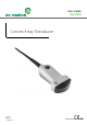


8802 User Guide
(BB0334-I)
9
2
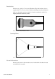
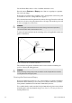
Fix the attachment bracket in position by tightening the attachment lock screw
(item A in Fig 3). Tighten the screw up to its “locking point”, after which it will
not be possible to tighten the screw anymore.
3
The biopsy attachment should now be fixed solidly to the transducer’s handle.
4
Using the needle guide locking screw (item B in Fig 3), adjust the needle guide
according to the size of needle to be used.
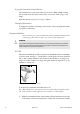
The distance from the guide channel entrance of the puncture attachment to the first
dot on the scan image puncture line is
52mm.
The distance between the dots is
10mm, see Fig 5 for details.
All parts of the puncture attachment can be autoclaved or disinfected by immersion
in a suitable solution.
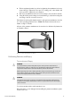
Figure 4. 8802 with UA 1250 mounted
Performing Puncture and Biopsy
Transcutaneous Biopsy
Cover the transducer with a sterile transducer cover.
If the transducer cover is damaged when attaching the puncture attachment, replace
it with a new cover.
WARNING
It is essential for the patient’s safety that only the correct puncture attachments, as
described in this guide, are used. Never use unauthorized combinations of transducers
and puncture attachments or other manufacturers puncture attachments.
Before beginning a puncture or biopsy procedure, always check that the type number of
the transducer and the type number or description of the puncture attachment match
exactly those displayed on the scanner monitor.
WARNING
The puncture line on the scan image is an indication of the expected needle path. The
needle tip echo should be monitored at all times so any deviation from the desired path
can be corrected.