
Specifications

MIL-STD-1472E
d. Actuators shall have sufficient separation to permit emor-free manipulation by the operator
(i.e.,the styluscannot inadvertentlycontactadjacentactuators).
5,4.3 .1.9.3 Sham. The surface of the actuator shall be indented to accept the point of the
stylus. The indentation shall be sufficiently deep to avoid slippage of the stylus during manipulation.
5.4.3.2 Continuous adjustment linear controls.
5.4.3.2.1 Levers.
5.4.3 .2.1.1 ~. Levers maybe used when high forces or large displacement are involved or
when multidimensional movements of controls are required.
5.4.3 .2.1.2 Coding. When several
leversare grouped near each other, the lever handIes shall
be coded.
5.4.3 .2.1.3 Labeling. When practicable, all levers shall be labeled as to function and direction
of motion.
5.4.3 .2.1.4 Limb supPo
rt. When levers are used to make fine or continuous adjustments,
support shall be provided for the appropriate limb segment as follows:
a. For large hand movements: elbow
b. For small hand movements: forearm
c. For finger movements: wrist.
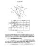
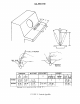
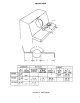
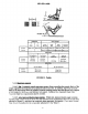
5.4.3 .2.1.5 Dimensions. The length of levers shall be determined by the mechanical advantage
needed. The diameter of spherical lever or grip handles shall conform to the criteria in Figure 17.
5.4.3 .2.1.6 Msistance. Lever resistance shall be within the limits indicated in Figure 17,
measumd as linear force applied to a point on the handle. (lWYI13 The right hand can supply slightly
more force than the lefi but the difference is not sign&ant. The same amount of push-pull force can
& applied when the control is aiong the median plane of the body as when it is directly in front of the
arm, 180 mm (7 in) from the median plane. When the control is in front of the opposite (unused) arm
only 75 percent as much force can be applied. When the control is 250-480 mm ( 10- 19in) forward
of the neutral seat reference point, twice as much push-pull
force canbe applied with two hands as
with one-hand. Outside this range tw~hand operation Ixxxmes less effective.)
5.4.3 .2.1.7 Displacement and separa
tion.
Controldisplacement(forthe seated operator)and
separation shall conform to the criteria in F@re 17.
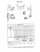
5.4.3.2.2 XXsDMxnrxmt@otcmic)iwmieks ~“
~-’@Y*~ea*
resistanceto movement awayfhm the
center (null) position, altbugh some have no spring. Joystick
controls may be used when the task requires precise or continuous control in two or mm related
dimensions. (The term “joystick” is used hereto refix primarily to controlsused for cursor placement
or pttcise adjustment.) ~pcmtmn~eeoumoy iwMwcAkaL&anpositicmir@ speed,
displacement joysticks should be selected over isometric joysticks. Displacement joysticks may also
he Iwd for various display functions such as data pickoff from a CRT and generation of fnx-drawn
graphics. In rate control applications, which ahw the Mower (cwor w htiking symbol) to
transit
beywl h G&c of lhc display,
indicatn~ shall hCpmwded to aid the operator in bringing the follower
back onto the display. Displacement joysticks used for rate control
shouldbe spring-loadedforreturn
~~~the
ccntcr u’hen the }Mn(!is wUIOVI’A
Pisplacemcnt irwsticks which hav? a rleadhanrl near the center
or hv<t~r~~ls
sh:lll not k LISC{I wi~h ;Imom;uic sequcncin: of n CRT
/’1