
Instruction manual
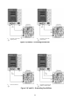
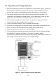
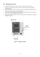
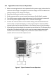
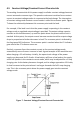
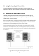
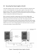
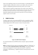
Table Of Contents
- 1 Safety Summary
- 2 Introduction
- 3 Quick Reference
- 4 Operating Instructions
- 4.1 Instrument Hook-Up
- 4.2 Typical Constant Voltage Operation
- 4.3 Setting Current Limit
- 4.4 Typical Constant Current Operation
- 4.5 Constant Voltage/Constant Current Characteristic
- 4.6 Saving the Power Supply’s Current State
- 4.7 Connecting Two Power Supplies in Series
- 4.8 Connecting Two Power Supplies in Parallel
- 5 RS232 Interface
- 6 Maintenance
- 7 Error Messages
- 8 Specifications
- 9 Service Information
- 10 Limited Three-Year Warranty

10
4.1 Instrument Hook-Up
1. Turn off the power supply and the equipment to be powered during hook-
up.
2. Connect the positive polarity of the device being powered to the red (+)
terminal of the power supply.
3. Connect the negative polarity of the device being powered to the black (-)
terminal of the power supply.
4.
Figure 3 illustrates the grounding possibilities.
a. If the negative polarity of the equipment or circuit being powered is also
the chassis or common, it may be grounded to earth by strapping the black
(-) terminal to the green ( ) terminal as shown in
Figure 3A.
b. Similarly, the positive polarity can be grounded by strapping the red (+)
terminal to the green ( ) terminal as shown in
Figure 3B.
c. If an earth ground reference is not required, the configuration of
Figure 3C
may be used. The scheme in
Figure 3C should also be used where it is not
known whether the chassis is common with either the positive or negative
polarity.
d. If the chassis or common of the equipment being powered is separate
from both the positive and negative polarity power inputs, use the
connection shown in
Figure 3D.
6. Observe proper polarity. If the circuit being powered is not equipped with
reverse polarity protection, damage to the circuit can result from reverse
polarity. Use color coded hook-up leads, for convenience in identifying
polarity, red for (+) and black for (-).
7. Make sure that the hook-up leads offer sufficient current capability and low
resistance between the power supply and the circuits being powered.