MODELS VSP6020, VSP2050, VSP4030 & VSP12010 High Power Switching DC Power Supplies Instruction Manual
TABLE OF CONTENTS SECTION DESCRIPTION PAGE NO.
Section 1 Test Instrument Safety WARNING Normal use of test equipment exposes you to a certain amount of danger from electrical shock because testing must sometimes be performed where exposed voltage is present. An electrical shock causing 10milliamps of current to pass through the heart will stop most human heartbeats. A Voltage as low as 35 volts dc or ac (rms.) should be considered dangerous and hazardous since it can produce a lethal current under certain conditions.
Section 2 General information 2.1 INTRODUCTION 2.2 FEATURE 2.3 MARKINGS 2.4 INTERFACE 2.5 SPECIFICATION 2.6 ORDERING INFORMATION 2.1 INTRODUCTION The VSP SERIES power supplies are designed to deliver power in constant voltage and constant current mode by switch mode conversion in sleek 1U high cabinet and in a 19’’ rack construction. This series comprises the two device soft switching technology that yields very high efficiency of conversion for dc-to-dc converter part.
Some of the features of the power supply are listed below: 2.2 FEATURES § § § § § § § § § § § § § § § § § § § § § MAINS OPERATED, WITH WIDE INPUT RANGE. POWER FACTOR CORRECTED INPUT. ISOLATED D.C. OUTPUT. 1200-WATT OUTPUT POWER CONSTANT VOLTAGE OPERATION FROM 0 TO FULL-SCALE LEVEL. CONSTANT CURRENT OPERATION FROM 0 TO FULL-SCALE LEVEL. OVER VOLTAGE CONTROL FACILITY. REMOTE SENSING FACILITY. PARALLELABLE CURRENT SHARING OUTPUT. HIGH OVERALL EFFICIENCY – 80% TYPICAL. VERY LOW OUTPUT RIPPLE AND NOISE.
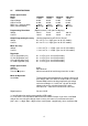
2.5 SPECIFICATIONS Output Specification Model Power Output Voltage Output Current Ripple rms. (10Hz to 1MHz) Noise (10Hz to 20MHz) Programming Resolution Voltage Current VSP6020* 1.2KW 0–60V 0–20A <10mV <45mVpp VSP2050* 1.2KW 0–20V 0–50A <15mV <45mVpp VSP4030* 1.2KW 0–40V 0–30A <10mV <45mVpp VSP12010* 1.
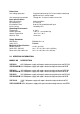
Protections Over voltage protection Over temperature protection Programmable through POT in local mode and through digital interface in remote mode. Through 90 °C. thermal switch on heat sink. Input specifications Mains Input Range Input Frequency Input Power Factor Inrush Current 95Vac to 264Vac. 47 To 63 Hz 0.99 On Full Load At Nominal Input. Limited By NTC Operating Environment Temperature Relative Humidity Storage Temperature Warm-up Time 0 - 50°C < 80% rh – non condensing - 20°C. to + 70°C.
Section 3 Installation 3.1 INTRODUCTION 3.2 UNPACKING 3.3 INPUT POWER REQUIREMENTS 3.4 SYSTEM CONFIGURATION 3.5 INSTALLATION 3.6 TEST EQUIPMENT REQUIREMENTS 3.1 Introduction VSP series power supply is configured, calibrated and tested prior to shipment. This unit is therefore ready for immediate use upon receipt. The initial physical inspections should be made to ensure that no damage has been sustained during shipment. 3.
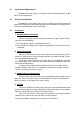
3.3 Input Power Requirements The Model VSP power supply is configured at the factory to operate from 95-264 VAC at 47-63 Hz power line. 3.4 System Configuration The Model VSP series power supply comes in ready to use fashion and does not require any configuration in the field for operation in the local mode. For analog interface refer to the connector details for the connections. 3.5 Installation 1. AC Input Power Connection Connect a 3-pin power mains cord to the available line supply.
3.6 Test Equipment Requirements The following instruments will be required to test the complete installation of the unit. 1). A four and half digit or better digital multimeter for verifying the voltage and current output of the unit. 2). A 20 MHz dual channel oscilloscope for verifying the Ripple in Output of the Source. 3). A Resistive load or an Electronic Load to take an input to suit the maximum output from the unit depending on the model and capacity of the channel of the Source.
Fig 3.
Section 4 Operating instruction 4.1 INTRODUCTION 4.2 FRONT PANEL DESCRIPTION 4.3 REAR PANEL DESCRIPTION 4.4 POWER ON CHECK 4.5 OPERATING INSTRUCTIONS IN LOCAL MODE 4.6 OPERATING INSTRUCTIONS IN ANALOG REMOTE INTERFACE 4.7 OPERATING INSTRUCTIONS IN DIGITAL INTERFACE 4.8 TRIP INDICATIONS 4.1 INTRODUCTION The VSP series Model is a variable switch mode power supply to provide wide range of DC supply from 0 to full-scale specified voltage.
4.2 FRONT PANEL DESCRIPTION Figure 4.1 shows layout of front panel. On the front panel following controls and indicators are provided. 1. 2. 3. 4. 5. 6. 7. 8. 9. Main ON/OFF switch with neon indication. 3 digit display for Voltage/ Set Voltage/ Set Over Voltage indication 3 digit display for Current/ Set Current indication. 10 turn POT for voltage control. 10 turn POT for current control. 10 turn POT for over voltage protection control. Push switch to view set parameters in SET mode.
12
13 1 14 15 6 2 16 12 7 3 11 4 8 17 10 17 19 20 9 17 18 5 21 22 24 26 23 Sr. No. 1 2 3 Description Input Line Cable Input Fuse Input R. F. Filter 4 5 6 7 8 9 10 11 12 13 VSP-PFC-1.2KW-1103D, PCB Input ON/OFF Switch Heat Sinks PFC Choke DC DC Converter Transformer VSP-DPM-CONT-1204D, PCB VSP-FAN-CNT-1103C, PCB VSPDDC-1.2KW-0704E, PCB Digital Interface PCB Output Power Terminals Sr. No.
4.3.1 LINE INPUT The mains input range is clearly indicated on rear panel. The unit comes standard with a U.S. standard plug and a mains input rating of 95VAC to 265VAC, 50/60Hz. 4.3.2 INPUT FUSE This fuse protects the unit against short circuits and over loading. The 20A fuse of type ’F’ is used for line input range 95Vac to 264Vac. 4.3.3 DC OUTPUT TERMINALS VSP models with upto 30 amp output ratings have a pair of 5mm brass studs is provided on the rear panel.
Pin no.14: Pin no.15: Pin no.16: Pin no.17: Pin no.18: Pin no.19: Pin no. 20: Pin no. 21: Pin no. 22: Pin no. 23: Pin no. 24: Pin no. 25: 4.3.6 N.C. +12 V- Remote on/off relay supply +ve. AGND3 - Common terminal for remote programming. Remote On/Off - Remote on/off relay. AMX- Output Current monitoring. (Factory set to 0 to 5 volts for full scale) VMX - Output Voltage monitoring. (Factory set to 0 to 5 volts for full scale) AGND3 - Common terminal for remote monitoring. N.C.
4.5 OPERATING INSTRUCTIONS IN LOCAL MODE These are the instructions for operating the source in local mode. Initially after Power ON Unit work in local mode.In local mode the power supply can be controlled through front panel potentiometers. Also Refer to the settings of 8Way DIP Switch provided on rear panel to operate in Local mode. Switch No. 1 Position On 2 On 3 On 4 On 5 On 6 OFF 7 On 8 On Refer fig. 3.
4.6 OPERATING INSTRUCTIONS IN ANALOG REMOTE INTERFACE The Remote analog interface is Provided to control the power supply with external analog signals.Before using the interface check the type of digital interface provided with the system. A slide switch no. 7 on 8 pin DIP switch array is provided at the rear panel to bypass digital and front panel pot controls. Ensure the position of slide switch is in off position when operating with external analog controls.
Refer figure 4.1b for external resistance programming 0 to 4.85kohms for full scale voltage and current . It also shows the load connections required in this mode. As shown in the figure for Voltage Control connect the resistance of 4.85 K ohms at pin 4 & common control pin 6 of 25 pin D Type connector & for Current control connect resistance between pin 9 & pin 6 (common control pin) of 25 pin D Type connector. 4.6.
Section 5 Maintenance 5.1 INTRODUCTION 5.2 PREVENTIVE MAINTENANCE 5.3 SERVICE INFORMATION 5.1 Introduction This chapter contains the problems that may occur in the field in the event of long use. The procedure to test the unit is explained under the proper section. The individual is advised to use the correct procedure provided for the purpose of operating the particular sequence to set proper voltages and current required to test the proper working of the unit.
When the unit is not turning ON. Check if the power ON/OFF switch is turned ON. Check whether fuse mounted on the rear panel is OK? If fuse is good then check the power cord. Please make sure that the power cord connecting to the unit is properly connected. Please also check the mains switch. Check the switch 8 on rear panel, it must be always in ON position for terminal voltage ON. When the Trip LED turns On and output turns OFF Check the settings of the over voltage potentiometer.
Section 6 Remote interface 6.1 INTRODUCTION 6.2 RS232C INTERFACE 6.3 RS232C OPERATION 6.4 IEEE-488 OPERATION 6.5 INTRODUCTION TO SCPI LANGUAGE 6.6 COMMAND SUMMARY 6.7 MANDATORY COMMANDS 6.8 INSTRUMENT COMMANDS 6.9 IEEE-4888 COMPLIANCE INFORMATION 6.10 SRQ HANDLING DETAILS 6.11 ERROR MESSAGES & REPORTING 6.12 APPLICATION PROGRAM EXAMPLES 6.
6.2 RS232C INTERFACE: The basic principle of RS232C operation is achieved by 3-wire interface. The 3-wire interface comprises of transmit pin (abbreviated as TXD), receive pin (abbreviated as RXD) and a common ground pin (GND). TXD pin of host is connected to the RXD pin of the instrument and the RXD pin of the host is connected to the TXD pin of the instrument and the third line connects the GROUNDs of the two sides. I.e. the TXD and RXD lines are cross-connected to the Host controller.
6.3.1 RS232 Data Format One Start Bit 6.3.2 8 Data Bits No Parity Bit 1 Stop Bit RS232 Connector Details On the rear panel of the unit, a 9 pin D-type male connector is provided for the RS232 communication. The DSR and DTR handshake lines are not used. But the interface cable which connects the COMM INTF on the instrument to the PC COM port (COM 1 or COM 2) should interconnect the RXD and the TXD line, such that the RXD input the instrument is the TXD output of the host controller or PC.
6.3.3 INSTALLATION OF RS232 CARD The RS232 Interface (ISO_RS232_CONV-1103 Card) card may come already installed, if ordered. If this interface is to be installed later, the card can be mounted on the rear panel of the unit using L-clamp provided on the card itself & following cards &cables shall be provided along.
6.3.4 RS232 Commands Following section deals with the commands set for RS232 interface. It specifies the syntax of each command, which reads the status of power supply or configures it to the requirements of users. NOTE: The command uses following notations = Indicates Null or space character (20H) = Indicates Arbitrary ASCII Response Data = Indicates Numeric Data = Indicates End of string character (ODH) 1.
4. Command: VOLT: PROT Description: Set Over Voltage Protection Limit of OUTPUT Function: This command sets the Over Voltage Protection Limit of the Power Supply output with the given in the command in Volts. The input VOLTAGE data is in Numeric Data format. Once this OVP limit is set, any time if the actual Output Voltage of the channel exceeds the OVP limit, the OUTPUT will be ‘TRIPed’. I.e.
9. Command : STAT? Description: Read Status Query. Function: This command reads the status of various events occurred in the system. The definition of events is given below B0: B1: B2: B3: B4: B5: B6: B7: Over voltage Trip Over Temperature Trip Power On event (Sets when unit is turn ON. The bit gets cleared after the quarry.
6.4.1 IEEE-488 Interface Configuration The IEEE-488 Interface is a parallel BUS for Communication in the Programmable Instruments. Multiple instruments can be connected on the same BUS and can be hooked up to a single HOST controller or computer. In order that instruments from different manufacturers can be built into the same system, it was necessary that all interfaces be compatible.
6.4.2 IEEE-488 Connector Details The instrument provides a standard 24 pin GPIB connector (marked as COMM INTF on the rear panel of the instrument) to connect it with the standard GPIB (IEEE488) bus. Refer FIG. 6.3 for connector types definition diagram. Description of the GPIB Signals is given below. PIN NO.
6.4.3 IEEE-488 Operational Sequence Guidelines Most interface communication tasks require a sequence of coded messages to be sent over the interface. It is recommended that a careful study of the available controller capabilities be made many of them assigning one programming instruction to these sequences. Different controllers will not necessarily have identical sequences or program instructions. The following sequences are recommendations only.
UNL SPE SPD SBN SBA 6.4.4 = = = = = Unlisten Serial Poll Enable Serial Poll Disable Status Byte Negative, where BIT 6 = 0 (BIT 7 is the MSB) Status Byte Affirmative, where BIT 6 = 1 (BIT 7 is the MSB) Installation procedure for GPIB interface option in the VSP series power Refer to the general assembly layout of the VSP series power supplies. In the standard units RS232 interface is provided by default. Accordingly, at the location no. 12 the RS232 interface card (ISO-RS232 CONV-0304A) is installed.
f) Compile the project. g) Connect line input to the unit. Keep the front panel output ON/OFF switch in OFF position. Turn the unit on with the input ‘Line’ switch. h) Run CSPY to download program in flash memory of the controller. i) j) Press the RESET button in the window and exit from CSPY. Turn OFF the unit & remove JTAG connector. This will complete the software installation for GPIB option.
Remove JP2,JP3, JP4 & JP5 From J3 of SBC-IEB Install JP1 From J2 Remove Jumper Link here. VSP-DPM-CONT To J7 To J5 To J1 of VSP-POT-IMON To J1 of INSTR-TO-GPIB 6.4.5 IEEE-488 Instrument Address Selection The instrument address is set manually using an eight way miniature switch near the interface connector on the rear panel. This DIP switch is normally marked with A0 to A7 to identify the proper switch. In our system, we refer A0 as switch 1 and an A7 as switch 8.
ADDRESS SWITCHES SWITCHES A4 0 0 0 0 0 0 0 0 0 0 0 0 0 0 0 0 1 1 1 1 1 1 1 1 1 1 1 1 1 1 1 A3 0 0 0 0 0 0 0 0 1 1 1 1 1 1 1 1 0 0 0 0 0 0 0 0 1 1 1 1 1 1 1 A2 0 0 0 0 1 1 1 1 0 0 0 0 1 1 1 1 0 0 0 0 1 1 1 1 0 0 0 0 1 1 1 A1 0 0 1 1 0 0 1 1 0 0 1 1 0 0 1 1 0 0 1 1 0 0 1 1 0 0 1 1 0 0 1 5-BIT DECIMAL CODE A0 0 1 0 1 0 1 0 1 0 1 0 1 0 1 0 1 0 1 0 1 0 1 0 1 0 1 0 1 0 1 0 00 01 02 03 04 05 06 07 08 09 10 11 12 13 14 15 16 17 18 19 20 21 22 23 24 25 26 27 28 29 30 HEX CODE 00 01 02 03 04 05 06 07 08 09 0A
6.4.6 Special Notes For the Controller Software Writer This section will provide some valuable hints to the controller software program writer for interfacing this Programmable Unit, through the communication interface. 1). Normal communication is in ASCII. The unit will accept both the lower case and upper case characters. 2). All commands for the units are in the IEEE-488.2 and SCPI format. 3). All mandatory commands for IEEE-488.2 are implemented in the unit. 4).
13). Before sending the unit into talk mode it is also advisable to Flush out the controller’s data-in buffer by giving a dummy read. This is required because some controller can keep the last data latched into its data-in Buffer. 14). If you send more than one query in a , only the LAST correct query will be processed and response will be given for last query. 15). No response can be read without giving a query. Otherwise the query error bit will be set & an error message is generated. 6.
USING WHITESPACE You must use Whitespace characters, [tab], or [space] to separate a parameter from a command keyword. Whitespace characters are generally ignored only in parameter lists. USING “?” COMMANDS The BUS controller may send commands at any time, but an SCPI instrument may only send responses when specifically instructed to do so. Only QUERY com mands (commands that end with a “?”) will instruct the instrument to send a response message.
DISCRETE PARAMETERS: Discrete parameters are used to program settings that have a limited number of values (like BUS, EXTernal, NORmal, and INVerted). They have a short forms and a long form just like command keywords. You can mix upper case and lower-case letters. Query responses will always return the short form in upper-case letters. BOOLEAN PARAMETERS: Boolean Parameters represent a single binary condition that is either TRUE or FALSE. For a false condition the instrument will accept “OFF” or “0”.
6.5.4 SCPI Status Model All SCPI instruments implement status registers in the same way. The status system records various instrument conditions in three register groups: The Status Byte register The Standard Event register and The Questionable Data register. The status byte register records high level summary information reported in the other register groups. The diagram on the next page illustrates the SCPI status system.
SCPI STATUS SYSTEM 40
The Status Byte Register The status byte summary register reports conditions from other status registers.Query data that is waiting in the instrument’s output buffer is immediately reported through the “message available” bit (bit 4). Bits in the summary registers are not latched. Clearing an event register will clear the corresponding bits in the status byte summary register. Reading all messages in the output buffer, including any pending queries will clear the message available bit.
TO INTERRUPT YOUR BUS CONTROLLER USING SRQ * * * * * Send a bus device clear message. Clear the event registers with the *CLS (clear status) command. Set the *ESE (standard event register) & *SRE (status byte register) enable masks. Send the *OPC? (Operation complete query) command and enter the result to assure synchronization. Enable your bus controller’s IEEE-488 SRQ interrupt. TO DETERMINE WHEN A COMMAND SEQUENCE IS COMPLETED.
Note: An error condition (standard event register bits 2,3,4 or 5) will always record one or more errors in the instrument’s error queue. Read the error queue using SYSTem: ERRor? The standard event register is cleared when: * You send a *CLS (clear status) command. * You query the event register using the *ESR? (Event status register) command. The standard event enable register is cleared when: * * You turn on the power to the instrument. You execute a *ESE 0 command.
BIT DEFINITIONS-QUESTIONABLE DATA REGISTER BIT VALUE 0 2 3 5 6 7 8 10 11 13 14 15 DESCRIPTION DEFINITION OVP trip OT trip OVP trip OT trip Not Used Not Used OVP trip OT trip OVP trip OT trip Not Used Not Used DECIMAL 1 4 8 32 64 128 256 1024 2048 8192 16384 32768 Channel 1 Over Voltage Trip Channel 1 Over Temperature Trip Channel 2 Over Voltage Trip Channel 2 Over Temperature Trip Always Set to 0 Always Set to 0 Channel 3 Over Voltage Trip Channel 3 Over Temperature Trip Channel 4 Over Voltage Trip Chann
SR NO. 1 2 3 4 5 6 7 8 9 10 11 12 13 IEEE-488.2 COMMON COMMANDS *CLS *ESE *ESE? *ESR? *IDN? *OPC *OPC? *RST *SRE *SRE? *STB? *TST? *WAI SR NO. 1 2 3 4 5 6 7 8 9 10 11 12 13 14 15 16 17 18 STATUS REPORTING COMMANDS SYSTem: ERRor? STATus: QUEStionable: EVENt? STATus: QUEStionable: ENABle? STATus: QUEStionable: CONDition? STATus :QUEStionable:ENABle STATus: OPERation: EVENt? STATus: OPERation: ENABle? STATus: OPERation: CONDition? STATus:OPERation:ENABle
NOTE: 6.6.1 = Null or space character (20H) = Arbitrary ASCII Response Data = Numeric Data = End of string character (OAH) = Channel Number operation. The format for giving the channel list is (@1) : Channel number 1 (@1,2) : Channel nos. 1 & 2. (@1,2:4) : Channel numbers 1,2,3,4. Brackets are compulsory. SPECIAL NOTES ON THE COMMANDS FOR VSP SERIES: 1). All commands for the unit are in the IEEE-488.2 and SCPI format. 2). All mandatory commands for IEEE-488.
6.7 MANDATORY COMMANDS This section explains in detail the IEEE-488.2 and SCPI MANDATORY common commands, which are supported by this Programmable Instrument. NOTE: = Null or space character (20H) = Arbitrary ASCII Response Data = Numeric Data = End of string character (OAH) = Channel Number operation. The format for giving the channel list is (@1) : Channel number 1 (@1,2) : Channel nos. 1 & 2. (@1,2:4) : Channel numbers 1,2,3,4. Brackets are compulsory. 1.
5. Command : Description : Function : *IDN? Identification Query This query command will read back the specific information about device. There are 4 fields in the response separated by commas. Field 1: Manufacturer (DEL) Field 2: Model number (XXXXXXX) Field 3: Serial number (0 if not available) Field 4: Version number (XX.YY) 6.
10. Command : Description : Function : 11. Command : Description : : This query command reads back the contents of the Status Byte Register in the Numeric Data format ranging from 0-255. Command : Description : Function : *TST? Self-Test Query. This query command causes an internal Self Test & reports whether the Test was completed successfully ( = 0 ) or detected any of the errors in the Self Test ( = non-zero ), which are discussed in detail under section 5.
15. 16. Command : Description : Function : STATus:QUEStionable:EVENt? Status Questionable Event Register Query. This query command returns the format (032767) value of the Questionable Event Register, (16 bit register) specific to instrument, to give the reason for Error. After this QUERY reads the register, the contents of the Status Questionable Data Event Register are cleared. Command STATus:QUEStionable:ENABle Set Enable bits for status Questionable Enable Register.
21. Command : Description : Function : 22. Command : STATus:OPERation:CONDition? Description : Read Status Operation condition register query. Function : This query will give the contents of Status Operation Condition Register in (0-32767) format, whose HEX value represents the Bit pattern of the register. This will always read as ‘0’ (ZERO). 23. Command : Description : Function 6.7.1 : STATus:OPERation:ENABle? Read Status Operation Enable Register Query.
NOTE: 1. 2. Command : Description : Function : Command : Description : Function : = Null or space character (20H) = Arbitrary ASCII Response Data = Numeric Data = End of string character (OAH ) = Channel Number operation. The format for giving the channel list is (@1) : Channel number 1 (@1,2) : Channel nos. 1 & 2. (@1,2:4) : Channel numbers 1,2,3,4. Brackets are compulsory. READ? Read Output Voltage and Current Query.
Volts. The input VOLTAGE data is in Numeric Data format. The above, indicates for which all CHANNELS the DATA has to be SET. The same data will be set on all the specified CHANNEL(S). If no such is provided the SOURce command will always SET to channel 1. For example to set 10.5 Volts on Channel 2, send the command as: SOURce:VOLTage 10.50(@2) For example to set 30 Volts on Channels 1&2,send the command as: VOLTage 3.00 E+1(@1:2) 3.
indicates for which all CHANNELS the LIMIT has to be SET. The same data will be set on all the specified CHANNEL(S). Once this limit is set, from that point onwards the output voltage can not be set to higher values than this. If you try to set higher value using SOURce:VOLTage command, the “ Execution error “ will be generated. At the same time the LIMITS can not be set to a value, which is more than the MAXimum ratings of the CHANNEL(S).
6. Command : Description : Function : OUTPut[:STATe]ON Set the Output relay to ON state for the specified channels. This command is used to switch on the output relay & thus to make the OUTPUT available at the output terminals. 7. Command : Description : Function : OUTPut[:STATe]OFF Set the Output relay to OFF state for the specified channels. This command is used to switch OFF the output relay & thus to disconnect the OUTPUT available at the output terminals. 8.
IEEE-488 INTERFACE COMPATIBILITY : Although the IEEE-488 Interface specification is called a standard, variations in implementation within the specifications are permitted. These variations determine the capabilities of the particular interface and a list of abbreviations are defined in the Standard Document to indicate to the User which Interface capabilities have been designed in. The TABLE 6.3 below gives the options, which are implemented in this instrument.
BIT DEFINITIONS-SERVICE REQUEST ENABLE (SRE) REGISTER BIT VALUE 0 1 2 DESCRIPTION DEFINITION Not Used Not Used Questionable Data 1 2 4 3 4 Not Used Message Available 8 16 5 6 7 DECIMAL Standard Event 32 Not Used 64 128 Always write with 0. Always write with 0. If this bit is set, an SRQ will be raised when one or more bits are set in the Questionable Data register (bits must be “enabled” in enable Register) Always write with 0.
To read the Status Byte Summary Register, send the IEEE-488 Serial Poll Message. Querying the Summary Register will return a Decimal value, which corresponds, to the binary - weighted sum of the bits, set in the register. Serial Poll will automatically clear the “ REQUEST SERVICE “ bit in the Status Byte Summary Register. No other bits are affected. Performing a Serial Poll will not affect the instrument functioning.
* No method is available to read the error queue from the front panel menu. * The error queue is cleared when power has been off or after a *CLS (clear status) command has been executed. * To read the error queue from the remote interface, send query as: SYSTem:ERRor? * Errors have the following format (the error string may contain up to 40 characters): -100,“Command error” ERROR QUEUE: As the errors and events are detected, they are placed in the queue. This queue is FIRST IN - FIRST OUT.
EXECUTION ERRORS Message: -200,”Execution error” A valid command could not be executed because of the unrecoverable TRIP condition in the related channel(s) or the numeric data given in the command exceeds the maximum allowed hard limits or the Soft Upper Limits which were set by the Limit commands. In such cases the instrument generates the Execution error.
Fig 4.
Fig 4.1b EXTERNAL RESISTANCE PROGRAMMING 0 TO 4.85KOHMS FOR FULL SCALE VOLTAGE & CURRENT NC NC VPROGI VPIN VPROGR AGND3 NC NC IPIN IPROGI IPROGR NC NC NC +12V AGND3 1 2 3 4 5 6 7 8 9 10 11 12 13 14 15 16 REMOTE ON/OFF 17 AMX 18 VMX 19 AGND3 20 NC 21 VPSET 22 VMSET 23 IPSET 24 IMSET 25 +S + -S NC CS BUS Ext. Resistance for voltage control Control Common Ext.
Section 7 Customer support B&K Precision offers courteous, professional technical support before and after the sale of their test instruments. The following services are typical of those available from our toll-free telephone number. 1-800-462-9832 l Technical advice on the use of your instrument. l Technical advice on special applications of your instrument. l Technical advice on selecting the test instrument for a given task. l Information on optional accessories for your instrument.
Section8 Warranty information Limited One-Year Warranty B&K Precision warrants to the original purchaser that its products and the component parts thereof, will be free from defects in workmanship and materials for a period of one year from date of purchase from an authorized B&K Precision distributor. B&K Precision will, without charge, repair or replace, at its option, defective product or component parts. Returned product must be accompanied by proof of the purchase date in the form of a sales receipt.
Section9 Service Information Warranty Service: Please go to our website, www.bkpreicsion.com & click on the service/ repair button to obtain an RMA #. Return the product in the original packaging with proof of purchase to the address below. Clearly state in writing the performance problem and return any leads, probes, connectors and accessories that you are using with the device. Non-Warranty Service: Please go to our website, www.bkpreicsion.com & click on the service/repair button to obtain an RMA #.
PN: 481-529-9-001 Printed in India Ó2004 B&K Precision Corp. 22820 Savi Ranch Parkway Yorba Linda, CA 92887 USA TEL: 714-921-9095 FAX: 714-921-6422 www.bkprecision.