
Instruction manual


4.3.1 LINE INPUT
The mains input range is clearly indicated on rear panel. The unit comes stan-
dard with a U.S. standard plug and a mains input rating of 95VAC to 265VAC, 50/60Hz.
4.3.2 INPUT FUSE
This fuse protects the unit against short circuits and over loading. The 20A
fuse of type ’F’ is used for line input range 95Vac to 264Vac.
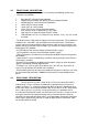
4.3.3 DC OUTPUT TERMINALS
VSP models with upto 30 amp output ratings have a pair of 5mm brass studs is
provided on the rear panel. Models above 30 amps have bus bars are provided. Output
polarity is shown near the terminal.
4.3.4 REMOTE SENSE CONNECTOR
6 Way terminals block is provided for remote sensing and current
share option.
1. +S: - Positive Sense terminal for remote sensing.
2. +Output: - Positive DC output terminal.
3. -Output: - Negative DC output terminal.
4. -S: - Negative Sense terminal for remote sensing.
5. NC
6. CS Bus: - Current share bus for parallel operation.
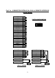
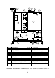
4.3.5
ANALOG INTERFACE CONNECTOR (Reference Fig. 4.1a and 4.1b in back of
manual)
25 Pin D type connector is provided for remote analog interface, it is factory set
to operate through the front panel controls.
Pin no. 1: N.C.
Pin no. 2: N.C.
Pin no. 3: VPROGI-1 mA (typical) Current source for voltage programming.
Pin no. 4: VPIN - Input for voltage programming.
Pin no. 5: VPROGR - Resistance programming (0 to 4.85KOhms for full-scale volt-
age)
Pin no. 6: AGND3 - Common terminal for remote programming.
Pin no. 7: N.C.
Pin no. 8: N.C.
Pin no. 9: IPIN - Input for Current programming.
Pin no.10: IPROGI- 1mA (typical) Current source for Current programming.
Pin no.11: IPROGR - Resistance programming (0 to 4.85KOhms for full-scale cur-
rent)
Pin no.12: N.C.
Pin no.13: N.C.
14